Skip to content
Beta

Relocate to STACKIT: VMware Migration Overview

Last updated on

Stackit LogoStackit Logo
STACKIT

Relocate to STACKIT: VMware Migration Overview

Plan VMware Relocate to STACKIT through discovery, target design, landing-zone readiness, migration waves, controlled cutover, validation, and optimization.

PLAN

Rapid Discovery

Start in Assess with a rapid inventory of VMware compute, storage, operating systems, and first capacity assumptions. Keep uncertainty visible for deeper Discovery instead of treating provisioned capacity as target sizing.

AssessRapid discoveryOverview In 4 trails

Rapid Discovery provides a fast, automated baseline of the current environment across on-premises and cloud landscapes. The focus is on quantifying the existing IT portfolio in a short time window, so teams can make early migration and commercial decisions with confidence.

At this stage, quantity and distribution matter more than deep application relationships.

Rapid Discovery builds an initial inventory of infrastructure and platform assets, including:

Compute footprint

Virtual machines and host counts.

Storage baseline

Storage capacity and storage classes.

OS landscape

Operating system families and versions.

Kubernetes baseline

Kubernetes cluster counts and baseline characteristics.

Database inventory

Database engines, sizes, and instance counts.

These metrics create the first fact-based view of migration scope.

The output of Rapid Discovery is a core input for:

  • Early price indication: Build the first STACKIT-aligned cost baseline.
  • Initial TCO view: Create a first total cost of ownership corridor.
  • Target capacity assumptions: Define initial cloud capacity and landing zone requirements.

This allows program stakeholders to align on financial direction and technical baseline before detailed planning starts.

Rapid Discovery is intentionally not a full application-level analysis. It does not include deep interviews with every application owner and does not aim to fully map all runtime dependencies.

That depth is covered in the subsequent Discovery phase, where infrastructure exports are enriched with targeted assessments and owner input to build a complete application picture.

Typical input sources include exports such as spreadsheets or similar inventory files from existing environments. This phase can be accelerated with AI-assisted tooling that extracts the required baseline metrics from uploaded datasets.

Rapid Discovery therefore acts as a prerequisite for structured cost indication and for shaping a realistic target environment strategy.

Use AI-assisted discovery assets when workload descriptions and inventory inputs need to be turned into first assessment and design artifacts for expert review.

Asset title
Framework
Asset type

The following diagram shows why Rapid Discovery is performed: raw source data is processed by tooling into a decision-ready baseline that supports early price indication and initial target sizing.

Swipe sideways to see the whole diagram
Rapid discovery process Input data is processed through rapid discovery tooling to produce decision-ready outputs for early migration choices. Input dataCMDB & inventory exportsAsset lists, hosts, base platform factsHypervisor & cloud reportsUsage, footprint, and utilization signalsPlatform listsKubernetes, database, and OS baselinesRapid discovery toolingIngest & normalize datasetsStandardize source records and schemaClassify & aggregate assetsConsolidate by technology and quantityApply assumptionsConfidence levels and growth factorsOutput informationConsolidated asset baselineFact base for scope and planningInitial STACKIT sizingFirst capacity assumptionsPrice indication & TCO corridorEarly cost orientation for decisions

A robust Rapid Discovery typically follows a clear sequence:

  1. Collect data from available sources (CMDB, hypervisor exports, cloud inventories, monitoring, storage reports, database lists).
  2. Standardize and consolidate records into a unified schema.
  3. Classify assets by workload type and technical characteristics.
  4. Aggregate results for management-level decision making.
  5. Validate initial assumptions with responsible stakeholders.

The objective is not a perfect target architecture. The objective is a reliable starting point with enough accuracy for early decisions.

Result quality depends heavily on source quality. Typical issues include duplicates, outdated entries, inconsistent naming, and missing performance data.

Recommended practice for this phase:

  • Document assumptions: Keep growth rates, consolidation factors, and capacity buffers explicit.
  • Flag unclear records: Mark uncertain entries instead of removing them too early.
  • Assign confidence levels: Label findings as high, medium, or low confidence.

This keeps cost indications traceable and allows focused refinement in the subsequent Discovery phase.

Rapid Discovery provides the volume baseline for early cost modeling. Captured assets are translated into STACKIT-relevant consumption dimensions, for example:

  • Compute sizing: Use vCPU and RAM as the baseline dimensions.
  • Storage class selection: Use storage capacity and I/O characteristics.
  • Managed service options: Use database engine and size classes.
  • Platform cost estimation: Use cluster and node counts.

Combined with operating assumptions (runtime profile, availability targets, growth trajectory), this produces a solid first price indication and an initial TCO corridor.

At the end of Rapid Discovery, the following outputs should be available at a minimum:

Consolidated asset baseline

Quantities per technology domain are consolidated in one baseline.

Meaningful segmentation

Assets are segmented by criticality, environment, and modernization potential.

Traceable assumptions

Assumptions and identified data gaps are documented transparently.

Initial cost indication

Cost ranges and primary drivers are available for early planning.

Prioritized candidates

A prioritized list for deeper Discovery activities is available.

These outputs establish the working baseline for architecture, planning, and governance in the next Assess steps.

Common Rapid Discovery risks include over-simplified categorization, incomplete source systems, or overestimating data maturity.

Proven countermeasures:

  • Combine sources: Use multiple data sources instead of relying on one source.
  • Review outliers: Check very large or very old systems systematically.
  • Align perspectives: Align finance and engineering interpretation to reduce bias.

This keeps the phase fast while preserving decision quality.

The handover point is reached when quantities, technology classes, and primary cost levers are sufficiently visible and open questions are clearly documented.

In Discovery, these open items are addressed through targeted owner interviews, deeper assessments, and dependency/compliance/operations analysis to build the full application-level picture.

STEP

Discovery

Enrich the estate baseline with dependencies, application criticality, operating constraints, and representative CPU, memory, storage, and network measurements needed for Relocate design and wave grouping.

Design and mobilizeDiscoveryOverview In 4 trails
Discovery source-to-decision flow Discovery separates technical and human-driven inputs, runs technical-first and human-enriched analyses, and hands over both insight streams to follow-on modules. Discovery inputsTechnical and automated discoveryInfrastructure inventoryCMDB, VM, database, middleware, storageRuntime and utilization dataCPU, memory, I/O, network and seasonalityIntegration and flow signalsNetwork paths, APIs, identity, data movementAssessment-driven human inputSecurity and compliance contextData classes, controls, audit requirementsOwner and business inputCriticality, release windows, lifecycle plansDiscovery analysis toolingTechnical-first analysesNormalize and correlateUnify records and technical identitiesDependency mappingInfer communication and couplingUtilization and sizing analysisEstimate baseline demand corridorsPreliminary segmentationCluster by stack and environmentHuman-driven analyses (application owner input)Criticality and risk calibrationValidate business impact and constraintsWave feasibility and sequencingReconcile dependencies with release windowsAssumption and gap registerTrack open points and confidenceHandover outputsTool-derived outputsDesignTarget architecture options and sizing factsLanding zonePlatform guardrails and account structure needsMigration planWave backlog, sequencing, and cutover windowsAssessment-validated outputsSecurity and complianceControl needs, data classes, remediation pointsOperating modelRole model, ownership boundaries, process impactBusiness caseValue/risk profile and modernization priorities
Discovery analysis flow combining technical evidence and application-owner input into migration decisions

Discovery is one of the first and most critical modules in the Design and Mobilize phase. It refines Rapid Discovery results and adds the depth needed to make architecture and migration-wave decisions with confidence.

The primary objective is to establish a realistic, evidence-based understanding of the current IT landscape, business priorities, and organizational readiness before detailed target design and migration planning are finalized.

Complete baseline

Create a reliable application and infrastructure baseline that goes beyond pure quantities.

Dependency transparency

Identify technical and process dependencies to avoid hidden migration blockers.

Business alignment

Link technical findings with business criticality, timelines, and risk tolerance.

Planning readiness

Produce decision-ready input for target design and migration-wave planning.

Inventory

Comprehensive capture of servers, virtual machines, databases, middleware, and applications.

Dependency analysis

Mapping of communication paths and runtime dependencies between systems and applications.

Resource utilization

Analysis of actual CPU, memory, storage, and I/O behavior over a representative period.

Operational context

Collection of backup, patching, SLA, compliance, and operational constraints.

Application owner input

Structured questionnaires and interviews to validate assumptions and close data gaps.

In practice, Discovery is often run together with STACKIT partners. Partners typically use their own tooling landscape to collect and normalize technical data into a central repository. Many programs also trigger targeted questionnaires for application owners directly from these tools to enrich technical findings with business and operational context.

This combined model improves speed and consistency while keeping stakeholder validation built into the process.

Two Evidence Streams: Technical vs. Human-Driven

Section titled “Two Evidence Streams: Technical vs. Human-Driven”

Discovery intentionally combines two evidence streams that complement each other:

  • Technically derived evidence: Tooling-generated findings from inventory exports, runtime metrics, and dependency signals. This stream provides scale, consistency, and repeatability.
  • Application-owner enrichment (human-driven): Validated business criticality, lifecycle intent, release constraints, and operational realities from owner interviews and questionnaires.

Neither stream is sufficient on its own. Technical evidence without owner context can misclassify critical workloads, while human input without technical grounding can hide coupling and capacity risks. Discovery quality depends on reconciling both streams into one decision-ready view.

The following diagram shows how Discovery transforms technical and stakeholder input into decision-ready outputs for the downstream modules.

Swipe sideways to see the whole diagram
Discovery source-to-decision flow Discovery separates technical and human-driven inputs, runs technical-first and human-enriched analyses, and hands over both insight streams to follow-on modules. Discovery inputsTechnical and automated discoveryInfrastructure inventoryCMDB, VM, database, middleware, storageRuntime and utilization dataCPU, memory, I/O, network and seasonalityIntegration and flow signalsNetwork paths, APIs, identity, data movementAssessment-driven human inputSecurity and compliance contextData classes, controls, audit requirementsOwner and business inputCriticality, release windows, lifecycle plansDiscovery analysis toolingTechnical-first analysesNormalize and correlateUnify records and technical identitiesDependency mappingInfer communication and couplingUtilization and sizing analysisEstimate baseline demand corridorsPreliminary segmentationCluster by stack and environmentHuman-driven analyses (application owner input)Criticality and risk calibrationValidate business impact and constraintsWave feasibility and sequencingReconcile dependencies with release windowsAssumption and gap registerTrack open points and confidenceHandover outputsTool-derived outputsDesignTarget architecture options and sizing factsLanding zonePlatform guardrails and account structure needsMigration planWave backlog, sequencing, and cutover windowsAssessment-validated outputsSecurity and complianceControl needs, data classes, remediation pointsOperating modelRole model, ownership boundaries, process impactBusiness caseValue/risk profile and modernization priorities

Typical Analysis Patterns in Discovery Tooling

Section titled “Typical Analysis Patterns in Discovery Tooling”

During Discovery, tooling commonly applies the following analysis patterns:

  • Record normalization: Merge heterogeneous exports into one coherent application model.
  • Dependency mapping: Detect communication paths, data exchange, and coupling patterns.
  • Criticality and risk scoring: Evaluate business impact, failure domain, and compliance exposure.
  • Utilization profiling: Build workload demand baselines for right-sizing and target planning.
  • Segmentation analysis: Cluster applications by readiness, constraints, and migration strategy fit.
  • Wave simulation: Model move groups and sequence options under dependency constraints.
  • Gap and assumption tracking: Keep unresolved findings transparent with confidence levels.

These analyses establish the technical fact base. The human-driven stream then validates, prioritizes, and contextualizes these findings for executable migration decisions.

Use AI-assisted discovery assets to structure workload inputs, service mapping, readiness findings, and R-strategy signals before architects validate the resulting discovery baseline.

Asset title
Framework
Asset type

  1. Aggregate source data from CMDBs, hypervisors, cloud inventories, monitoring, and export files.
  2. Normalize and consolidate records into a common application-centric model.
  3. Discover and validate dependencies (network, data, identity, integration, and batch flows).
  4. Enrich with owner input on criticality, lifecycle, constraints, and migration feasibility.
  5. Classify workloads for migration strategy options and wave sequencing.
  6. Validate findings with architecture, security, platform, and business stakeholders.
  • Reduces migration risk: Early visibility of hidden dependencies lowers outage and rollback risk.
  • Improves wave planning: Workloads can be grouped realistically by coupling, criticality, and readiness.
  • Prevents over/under-sizing: Measured utilization replaces assumptions in target capacity planning.
  • Supports governance: Security, compliance, and operational constraints are addressed before rollout.
  • Strengthens stakeholder buy-in: Shared facts improve decision quality across business and IT.

Discovery outputs are directly reused by the next modules in Design and Mobilize:

Design

Uses dependency, capacity, and risk insights to shape target architecture options.

Security and Compliance

Uses data classification and control gaps to define prioritized security requirements.

Landing Zone

Uses platform and governance constraints to define foundational setup decisions.

Migration Plan

Uses move groups, criticality, and sequencing constraints for realistic wave planning.

Operating Model and Business Case

Uses ownership, process impact, and value/risk signals for staffing and investment priorities.

At minimum, Discovery should produce the following outputs:

  • Consolidated application baseline: Mapped inventory by domain, environment, and criticality.
  • Dependency map: Verified upstream/downstream relationships and integration touchpoints.
  • Utilization profile: Evidence-based resource behavior and sizing assumptions.
  • Constraint register: Security, compliance, licensing, and operational constraints.
  • Migration readiness view: Prioritized candidates, risks, and sequencing recommendations.

These outputs are essential prerequisites for continuing with detailed design work and a credible migration plan.

STACKIT LogoSTACKIT Logo
VMware Relocate Source Readiness STACKIT · Runbook Open asset ↗

Use this runbook before assigning VMware virtual machines to a Relocate wave. It turns discovery evidence into a technical source-readiness decision and separates common VMware checks from the requirements of Cloudbase Coriolis and Hystax Acura.

The output is a per-VM readiness record with supported, conditional, or blocked status. Resolve blocked items before replication begins instead of moving uncertainty into the cutover window.

  • VM inventory: vCenter, cluster, host, datastore, VM hardware version, firmware, operating system, VMware Tools state, virtual disks, controllers, NICs, addresses, and attached devices.
  • Workload context: Application owner, criticality, dependencies, consistency requirements, recovery objectives, allowed downtime, and rollback tolerance.
  • Performance evidence: Representative CPU, memory, IOPS, throughput, latency, queue, capacity, and growth data rather than provisioned VMware capacity alone.
  • Migration path: Selected tool, Coriolis or Acura, and its current source and target compatibility matrix.
  1. Confirm that the guest operating system, architecture, file systems, partition layout, and boot mode are supported by the selected tool and STACKIT target.
  2. Record BIOS or UEFI firmware, Secure Boot, virtual disk controllers, NIC models, static routes, and guest-specific drivers that may require conversion or replacement.
  3. Identify encrypted disks, Raw Device Mappings, shared disks, independent disks, passthrough devices, nested virtualization, and removable media. Treat each unsupported attachment as a blocker or design an explicit replacement.
  4. Verify current VMware Tools health. Even where the migration tool is agentless, current guest tools improve inventory quality, snapshot coordination, and controlled shutdown behavior.
  5. Confirm operating-system licensing and activation behavior after the virtual hardware and cloud environment change.
  1. Resolve active alarms, failed backups, orphaned snapshots, snapshot consolidation warnings, and file-system or volume errors before replication.
  2. Verify that application-consistent or crash-consistent snapshots meet the workload’s recovery requirements. Databases and other stateful systems may need application quiescing or native replication in addition to VM replication.
  3. Reserve datastore capacity for migration snapshots and change tracking. Include current growth, expected write rate, replication duration, and retry margin in the capacity decision.
  4. Test backup restoration independently of the migration tooling and retain a recovery point that predates the first migration operation.
  1. Measure available bandwidth, latency, packet loss, and the daily data-change rate between source and target. Confirm that the initial copy and subsequent deltas fit the planned wave schedule.
  2. Validate DNS, NTP, MTU, proxy, routing, NAT, and firewall behavior across management and data paths. Record every required source, destination, protocol, port, and owner.
  3. Use dedicated, least-privilege service accounts for vCenter or ESXi and the STACKIT target. Validate API access and certificate trust before creating endpoints.
  4. Confirm target address allocation, security groups, DNS changes, load-balancer changes, and the traffic-switch mechanism. Replication software does not replace the cutover network runbook.

Apply these checks when Cloudbase Coriolis is selected:

  1. Validate the supported VMware source and STACKIT destination endpoint versions against the Coriolis release used for the wave.
  2. Create and test the VMware endpoint with a dedicated API identity. Confirm that Coriolis can enumerate the selected VMs, disks, networks, and storage required by the migration scope.
  3. Create and validate the STACKIT destination endpoint, then define source and destination minion pools with enough worker capacity and concurrency for the planned wave.
  4. Define source-to-target network and storage mappings before creating Transfer and Deployment definitions. Review the destination machine type, boot volume, data volumes, and security groups.
  5. Validate minion-worker and data-transfer connectivity required by the deployed architecture. Do not assume that HTTPS access to the Coriolis user interface proves migration-path readiness.
  6. Review guest conversion and OS-morphing support, including bootloader, storage driver, network driver, and cloud initialization behavior. Mark workloads requiring manual remediation.

The Coriolis STACKIT Installer deploys and configures the Coriolis appliance on STACKIT. It does not create VMware permissions, resolve unsupported source devices, size target VMs, or validate the source-to-target transfer path.

Cloud Framework Coriolis STACKIT Installer Deploy the Coriolis appliance reproducibly after source and target prerequisites are understood. Open page

Apply these checks when Hystax Acura is selected:

  1. Confirm that VMware Tools is installed and running on every selected VM.
  2. Verify that Changed Block Tracking and VMware snapshots can be used for the selected virtual disks and that no conflicting snapshot operation is active.
  3. Keep at least 10 percent free capacity on source datastores and increase that margin for high-change workloads or long replication windows.
  4. Provide the documented vSphere API permissions and validate connectivity to vCenter or ESXi on TCP ports 443 and 902 from the Acura components that perform discovery and replication.
  5. Deploy and validate the required Hystax replication agents on the source ESXi hosts before scheduling the first full replication.
  6. Plan at least one isolated test migration. Traffic redirection, DNS changes, and application freeze remain explicit cutover-runbook activities outside Acura replication.

Record the result for every VM and preserve the evidence used for the decision.

  • Guest compatibility: Pass with a supported operating system, boot mode, disk layout, and conversion path. Block on an unsupported device, encryption method, architecture, or boot path.
  • Source integrity: Pass with a healthy VM, tested recovery point, and safe snapshot state. Block on a consolidation error, failed backup, or insufficient datastore capacity.
  • Performance baseline: Pass with representative CPU, memory, storage, and growth measurements. Block when only provisioned capacity or incomplete peak-window data is available.
  • Access: Pass with tested least-privilege endpoint credentials and certificate trust. Block on missing API permissions or unmanaged shared credentials.
  • Transfer path: Pass with measured capacity and validated routing, ports, DNS, NTP, and MTU. Block on firewall gaps, unstable links, or a copy duration outside the wave schedule.
  • Cutover inputs: Pass with target mappings, validation tests, a rollback trigger, and source retention. Block on an undefined traffic switch or rollback path that cannot be tested.

Approve a VM for replication only when every blocker has an owner and resolution date. Conditional items must have an executable remediation step in the wave runbook; observations without impact can remain in the evidence record.

LIFT

Design

Confirm that the workload should remain VM-based and that moving its runtime placement with minimal redesign fits better than a Rehost rebuild or a platform change.

Design and mobilizeDesignRelocate In 1 trail
R-strategy migration method Decision flow from discovery to production with the seven R-strategies: Relocate, Rehost, Replatform, Repurchase, Refactor, Retain, and Retire. R-strategy migration methodFrom discovery and path selection through the seven R-strategies to validation, transition, and production.DiscoveryDiscoveryAssess / prioritizeAssess / prioritizeDetermine migration pathDetermine migration pathValidationValidationTransitionTransitionProductionProductionRelocateRelocate(move VM)Define Landing ZoneDefine Landing ZoneUse migration toolsUse migration toolsAUTOMATEMANUALInstallInstallConfigConfigDeployDeployValidation & handoverRehostingRehosting(move application)Define Landing ZoneDefine Landing ZoneUse migration toolsUse migration toolsAUTOMATEMANUALInstallInstallConfigConfigDeployDeployReplatformingReplatforming(lift and reshape)Define Landing ZoneDefine Landing ZoneMap Target PlatformMap Target PlatformAdapt Platform StackAdapt Platform StackRepurchasingRepurchasing(replace, drop and shop)Purchase COTS/SaaS and licensingPurchase COTS/SaaS and licensingMigrate business processMigrate business processRefactoringRefactoring(re-architecting applications)Redesign application/ infrastructure architectureRedesign application/ infrastructure architectureApp code developmentApp code developmentFull ALM/SDLCFull ALM/SDLCIntegrationIntegrationRetain/moveRetain/movekeep for now or move laterRetire/decommissionRetire/decommissionLanding zone foundationLanding zone foundationShared platform base for all paths
R-strategy method with seven migration paths and Relocate as the VM-estate movement path

Relocate moves workloads with minimal architectural change, typically by transferring virtualization estates to a STACKIT-compatible target setup. The goal is fast transition with controlled risk, not immediate cloud-native modernization.

In practical terms, Relocate keeps the existing VM operating pattern largely intact. The main change is the runtime location and surrounding platform controls, not the workload runtime model itself.

Relocate and Rehost are both low-change paths, but they differ in migration depth and adaptation scope.

  • Relocate in STACKIT: Focuses on moving existing VM-centric estates into a compatible STACKIT target with as little workload reshaping as possible.
  • Rehost in STACKIT: Focuses on workload-level lift-and-shift into STACKIT target runtimes, including explicit runtime mapping, cutover design, and runbook standardization for factory scale.
  • Operational consequence: Relocate is usually the fastest path for estate movement, while Rehost is usually the clearer path for repeatable application-wave delivery.
  • Planning consequence: Choose Relocate when preserving current operating patterns is the priority; choose Rehost when migration repeatability across many applications is the priority.

Relocate can be delivered in two operational variants, depending on estate size, heterogeneity, and cutover risk profile.

  • Tool-assisted relocate: Preferred for large-scale migration programs where throughput, consistency, and repeatable wave handling are required.
  • Controlled manual relocate: Suitable for smaller or exceptional workloads that require more manual sequencing.
  • Shared quality baseline: Both variants still require the same cutover controls, rollback design, and Day-1 operations readiness.
  • Time-critical transitions: Exit timelines or data residency deadlines require rapid movement.
  • Low change tolerance: Business cannot absorb major application refactoring in the current phase.
  • Known workload behavior: Existing VM-based patterns are stable and operationally understood.
  • Deferred modernization strategy: Cloud-native optimization is planned as a later wave.

Landing zone compatibility

Validate network segmentation, IAM model, and security controls before migration starts.

Performance and sizing

Re-baseline VM sizing and storage profiles to avoid overprovisioning after move.

Operational controls

Preserve monitoring, backup, and recovery controls from day one in the target environment.

Large data volume handling

For very large VM data sets, define pre-seeding, delta-sync windows, and transfer throttle rules before cutover to avoid extended outage windows.

Future modernization path

Record explicit trigger points for follow-up replatform/refactor decisions.

In Relocate, the data path is often implicit because the full VM (including attached storage) is moved. Even so, large data footprints still require explicit design decisions:

  • Network connectivity capacity: Validate end-to-end throughput, latency, and transfer path stability for the planned migration window.
  • Storage class fit: Align source and target storage classes with required IOPS/throughput characteristics before cutover.
  • Pre-seed strategy: Transfer baseline volumes before cutover where possible.
  • Delta synchronization: Minimize final downtime window by only syncing latest changes during cutover.
  • Integrity checks: Define checksum and sample-read validation for migrated disks.
  • Rollback checkpoints: Keep source snapshot retention until target acceptance is confirmed.
  1. Confirm baseline workload dependencies and operational constraints.
  2. Define target stack mapping in STACKIT and required network/security controls.
  3. Design migration sequence, downtime assumptions, and rollback model.
  4. Validate operational readiness (monitoring, backup, incident handling).
  5. Document post-move optimization backlog and ownership.
  • Approved design decision record with scope, assumptions, and governance sign-off.
  • Validation evidence package for security, compliance, and operational readiness.
  • Strategy-specific migration runbook draft from the Design phase.
  • Handover package for Migration Factory Setup and wave planning.
  • Relocate decision record with trade-offs and exit criteria.
  • Target stack mapping per workload.
  • Cutover and rollback design.
  • Day-1 operations checklist.
  • Post-relocation optimization backlog.

Define the target landing zone controls for the Relocate wave before run start. Confirm account boundaries, network segmentation, and baseline controls so existing VM operating patterns can be transferred without violating platform governance.

Define the tool-assisted run path for scalable and repeatable Relocate waves. Set execution roles, migration batches, and rollback checkpoints up front so large VM estates can be moved with consistent controls across waves.


Asset title
Framework
Asset type

Describe manual installation steps for workloads that are not migrated with tools. Include OS baseline, package dependencies, and host preparation criteria to keep exception paths compatible with standard operations.

  • Prepare target VM and storage: Create target VM, attach required disks, and align CPU/memory sizing with measured source behavior.

  • Install required base components: Install hypervisor guest tools, OS packages, and runtime prerequisites needed to boot and operate the workload.

  • Transfer workload artifacts: Copy disk images, boot files, and service units/scripts using a controlled transfer path.

  • Validate boot and host baseline: Verify successful boot, filesystem mount integrity, and core network reachability before configuration.

  • Runbook Blueprint
  • Cloud Design Patterns

Document manual target-side configuration and parameter alignment. Record security policies, IAM assignments, backup defaults, and monitoring baselines so moved workloads are operationally equivalent from day one.

  • Align system and application parameters: Apply hostname, DNS, time sync, and environment settings required by the workload.

  • Configure security and access model: Apply access policies, service credentials, and administrative boundaries for the target environment.

  • Enable operations baseline: Configure monitoring agents, log forwarding, backup jobs, and restore-test hooks.

  • Run configuration parity checks: Compare key runtime parameters with source baseline and document accepted differences.

  • Runbook Blueprint
  • Migration Plan

Define manual deployment sequencing and handover checks. Define freeze windows, acceptance checks, and ownership transfer steps to prevent ambiguous handover during cutover.

  • Execute cutover sequence: Stop source writes, run final delta sync, and activate the target workload in the approved order.

  • Validate service behavior: Run smoke and critical-path tests, including connectivity to dependent systems.

  • Stabilize and monitor: Observe key metrics, error rates, and operational alerts during the agreed Hypercare window.

  • Finalize ownership transfer: Confirm support responsibilities, escalation paths, and rollback closure criteria.

  • Migration Plan
  • Runbook Blueprint

Specify how Relocate outputs enter the common validation gate. Bundle technical evidence, risk log updates, and operational acceptance status so downstream wave governance can decide release without rework.
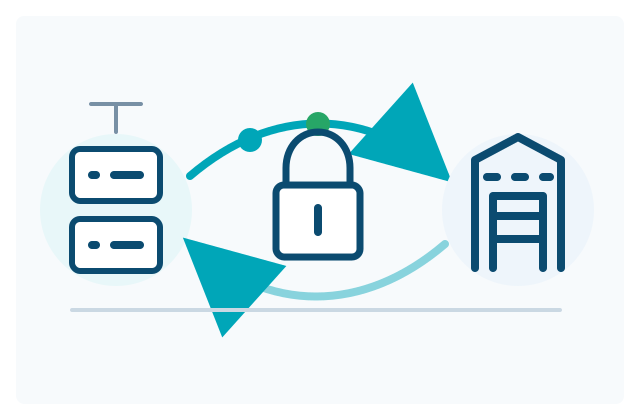
Relocate moves workloads with minimal architectural change, typically by transferring virtualization estates to a STACKIT-compatible target setup. The goal is fast transition with controlled risk, not immediate cloud-native modernization.

In practical terms, Relocate keeps the existing VM operating pattern largely intact. The main change is the runtime location and surrounding platform controls, not the workload runtime model itself.

Relocate and Rehost are both low-change paths, but they differ in migration depth and adaptation scope.

  • Relocate in STACKIT: Focuses on moving existing VM-centric estates into a compatible STACKIT target with as little workload reshaping as possible.
  • Rehost in STACKIT: Focuses on workload-level lift-and-shift into STACKIT target runtimes, including explicit runtime mapping, cutover design, and runbook standardization for factory scale.
  • Operational consequence: Relocate is usually the fastest path for estate movement, while Rehost is usually the clearer path for repeatable application-wave delivery.
  • Planning consequence: Choose Relocate when preserving current operating patterns is the priority; choose Rehost when migration repeatability across many applications is the priority.

Relocate can be delivered in two operational variants, depending on estate size, heterogeneity, and cutover risk profile.

  • Tool-assisted relocate: Preferred for large-scale migration programs where throughput, consistency, and repeatable wave handling are required.
  • Controlled manual relocate: Suitable for smaller or exceptional workloads that require more manual sequencing.
  • Shared quality baseline: Both variants still require the same cutover controls, rollback design, and Day-1 operations readiness.
  • Time-critical transitions: Exit timelines or data residency deadlines require rapid movement.
  • Low change tolerance: Business cannot absorb major application refactoring in the current phase.
  • Known workload behavior: Existing VM-based patterns are stable and operationally understood.
  • Deferred modernization strategy: Cloud-native optimization is planned as a later wave.

Landing zone compatibility

Validate network segmentation, IAM model, and security controls before migration starts.

Performance and sizing

Re-baseline VM sizing and storage profiles to avoid overprovisioning after move.

Operational controls

Preserve monitoring, backup, and recovery controls from day one in the target environment.

Large data volume handling

For very large VM data sets, define pre-seeding, delta-sync windows, and transfer throttle rules before cutover to avoid extended outage windows.

Future modernization path

Record explicit trigger points for follow-up replatform/refactor decisions.

In Relocate, the data path is often implicit because the full VM (including attached storage) is moved. Even so, large data footprints still require explicit design decisions:

  • Network connectivity capacity: Validate end-to-end throughput, latency, and transfer path stability for the planned migration window.
  • Storage class fit: Align source and target storage classes with required IOPS/throughput characteristics before cutover.
  • Pre-seed strategy: Transfer baseline volumes before cutover where possible.
  • Delta synchronization: Minimize final downtime window by only syncing latest changes during cutover.
  • Integrity checks: Define checksum and sample-read validation for migrated disks.
  • Rollback checkpoints: Keep source snapshot retention until target acceptance is confirmed.
  1. Confirm baseline workload dependencies and operational constraints.
  2. Define target stack mapping in STACKIT and required network/security controls.
  3. Design migration sequence, downtime assumptions, and rollback model.
  4. Validate operational readiness (monitoring, backup, incident handling).
  5. Document post-move optimization backlog and ownership.
  • Approved design decision record with scope, assumptions, and governance sign-off.
  • Validation evidence package for security, compliance, and operational readiness.
  • Strategy-specific migration runbook draft from the Design phase.
  • Handover package for Migration Factory Setup and wave planning.
  • Relocate decision record with trade-offs and exit criteria.
  • Target stack mapping per workload.
  • Cutover and rollback design.
  • Day-1 operations checklist.
  • Post-relocation optimization backlog.

Define the target landing zone controls for the Relocate wave before run start. Confirm account boundaries, network segmentation, and baseline controls so existing VM operating patterns can be transferred without violating platform governance.

Define the tool-assisted run path for scalable and repeatable Relocate waves. Set execution roles, migration batches, and rollback checkpoints up front so large VM estates can be moved with consistent controls across waves.

Asset title
Framework
Asset type

Describe manual installation steps for workloads that are not migrated with tools. Include OS baseline, package dependencies, and host preparation criteria to keep exception paths compatible with standard operations.

  • Prepare target VM and storage: Create target VM, attach required disks, and align CPU/memory sizing with measured source behavior.

  • Install required base components: Install hypervisor guest tools, OS packages, and runtime prerequisites needed to boot and operate the workload.

  • Transfer workload artifacts: Copy disk images, boot files, and service units/scripts using a controlled transfer path.

  • Validate boot and host baseline: Verify successful boot, filesystem mount integrity, and core network reachability before configuration.

  • Runbook Blueprint
  • Cloud Design Patterns

Document manual target-side configuration and parameter alignment. Record security policies, IAM assignments, backup defaults, and monitoring baselines so moved workloads are operationally equivalent from day one.

  • Align system and application parameters: Apply hostname, DNS, time sync, and environment settings required by the workload.

  • Configure security and access model: Apply access policies, service credentials, and administrative boundaries for the target environment.

  • Enable operations baseline: Configure monitoring agents, log forwarding, backup jobs, and restore-test hooks.

  • Run configuration parity checks: Compare key runtime parameters with source baseline and document accepted differences.

  • Runbook Blueprint
  • Migration Plan

Define manual deployment sequencing and handover checks. Define freeze windows, acceptance checks, and ownership transfer steps to prevent ambiguous handover during cutover.

  • Execute cutover sequence: Stop source writes, run final delta sync, and activate the target workload in the approved order.

  • Validate service behavior: Run smoke and critical-path tests, including connectivity to dependent systems.

  • Stabilize and monitor: Observe key metrics, error rates, and operational alerts during the agreed Hypercare window.

  • Finalize ownership transfer: Confirm support responsibilities, escalation paths, and rollback closure criteria.

  • Migration Plan
  • Runbook Blueprint

Specify how Relocate outputs enter the common validation gate. Bundle technical evidence, risk log updates, and operational acceptance status so downstream wave governance can decide release without rework.

Secured VMware-to-STACKIT transfer path
OPS

Map Target Capacity

Use this guide to define the initial STACKIT compute and storage profile for VMware workloads that will be relocated as virtual machines. It converts measured demand into an explicit target mapping without copying provisioned vCPU, memory, or datastore capacity one to one.

Initial target sizing protects the migration and cutover. It is not the final optimization decision. Review the profile again after the workload has produced representative telemetry on STACKIT.

Collect measurements over a period that includes normal operation, peak windows, batch processing, backup activity, month-end or seasonal events, and known incidents.

  • CPU: Capture consumed CPU, peak and p95 demand, ready or contention time, and sustained load duration. Do not use provisioned vCPU count as the sole input.
  • Memory: Capture active and consumed memory, working-set peaks, ballooning, swapping, and cache behavior. Do not assume allocated VMware memory is continuously required.
  • Storage capacity: Capture used capacity, growth rate, retention, snapshot, backup, and temporary workspace needs. Do not migrate abandoned snapshots or unused disks without review.
  • Storage performance: Capture read and write IOPS, throughput, latency, queue depth, block size, and peak duration per disk. Do not select a class from capacity or average IOPS alone.
  • Network: Capture ingress, egress, connection count, burst profile, latency, and packet-loss sensitivity. Include backup and replication traffic.
  • Availability: Capture recovery objectives, failure-domain requirements, maintenance tolerance, and restart behavior. Do not treat a larger VM as an availability design.

Document the source, time range, percentile, missing samples, growth assumptions, and confidence for every measurement. Apply a named safety margin where the evidence is incomplete instead of hiding uncertainty in an oversized target.

STACKIT machine types are predefined hardware configurations. Individual vCPU and RAM combinations cannot be assembled beyond the offered variants, so selection is a two-dimensional fit rather than a direct conversion of the VMware configuration.

From the STACKIT docsMachine types - EU01 › Machine type namesSource updated 24.07.2026 · copied 05.10.2026

Example of a machine type name: c1a.8d

The first part of the name, e.g. “c1a.8d”, is the variant of a machine type. Currently, there are the following variants:

What is this?

This section is copied from the STACKIT docs automatically, several times a day. It cannot be changed here. Changes belong in the STACKIT docs.

The generation, processor architecture, available sizes, and exact memory values vary by region and can change over time. Resolve the current catalog in the target region before approving a wave.

  1. Convert CPU measurements into required target cores for the design load, then add explicit peak, growth, and measurement-confidence headroom.
  2. Convert the observed memory working set into required RAM and add headroom for guest overhead, cache behavior, growth, and cutover uncertainty.
  3. Identify the machine-type family whose CPU-to-memory ratio wastes the least capacity while meeting both requirements.
  4. Select the smallest current type in that family that satisfies CPU and RAM simultaneously; record which dimension determines the size.
  5. Decide explicitly between CPU-overprovisioned and d types. Prefer a non-overprovisioned type when sustained CPU demand, latency sensitivity, or observed contention makes predictable CPU access a requirement.
  6. Validate processor architecture, operating-system support, licensing, availability-zone placement, quotas, and maintenance behavior.
  7. Test the selected type with a representative pilot and preserve the next larger and smaller valid types for rollback and later rightsizing decisions.

Do not infer equivalent performance from vCPU count alone. Processor generation, overprovisioning, guest drivers, workload concurrency, and source contention all influence the observed result.

Treat storage capacity, performance, and availability as separate decisions.

  1. Size each root and data volume from used data, expected growth, file-system needs, snapshots, backup behavior, and temporary migration workspace.
  2. Keep disks separate where workload consistency, backup policy, performance isolation, or future growth requires independent control.
  3. Choose Single AZ or Metro according to the workload’s failure-domain design. Metro volumes are mirrored across availability zones; this does not remove the need for backups or application-level recovery design.

A STACKIT Block Storage performance class defines the maximum IOPS and throughput for the complete volume. The class is independent of volume size, and all consumers of that volume, including VM and backup reads, share its performance envelope.

  1. Establish required read and write IOPS, throughput, latency, block-size distribution, and concurrency for each target volume.
  2. Add explicit peak, backup, recovery, and growth headroom to IOPS and throughput independently.
  3. Select the lowest current performance class that satisfies both limits. A class that passes IOPS but fails throughput, or the reverse, is not sufficient.
  4. Validate the choice during replication and isolated test migration, when copy traffic may expose a different bottleneck from normal application operation.
  5. Record observed latency, I/O wait, queue depth, IOPS, and throughput after cutover for the Optimize review.
From the STACKIT docsService plans › Currently available Service Plans (performance classes)Source updated 22.04.2026 · copied 05.10.2026

The following table lists currently available performance classes for the EU01 region:

IOPS - Input/Output Operations per second

Throughput - Throughput in Megabytes per second

Thus, the classes used can be distinguished in detail based on the naming. Example: “Block Storage Premium - Performance Class 2” corresponds to SSD hard disks with max. 1000 IOPS and max. 100 Mbyte/s throughput.

What is this?

This section is copied from the STACKIT docs automatically, several times a day. It cannot be changed here. Changes belong in the STACKIT docs.

The table shows the EU01 catalog. Always resolve the current values for the target region.

Create one version-controlled mapping row per VM and volume.

  • Source VM and workload: Stable inventory identifier and application mapping.
  • Target region and placement: Region, availability zone or Metro requirement, and quota result.
  • Machine type: Exact type, CPU and RAM requirement, governing dimension, headroom, and overprovisioning decision.
  • Root volume: Capacity, performance class, boot assumptions, and recovery assumptions.
  • Data volumes: Source-to-target disk mapping, capacity, performance class, and consistency group.
  • Network: Target network, addresses, security groups, DNS, and bandwidth expectation.
  • Validation thresholds: CPU, memory, latency, IOPS, throughput, application SLO, and observation window.
  • Adjustment options: Approved larger and smaller type, storage alternative, change method, and rollback condition.

Approve the mapping only when the target profile, expected cost, quota, tool mapping, and acceptance thresholds are all known. Feed the exact mapping into the Coriolis or Acura test migration rather than choosing target resources during cutover.

BASE

Landing Zone

Establish the governed cloud foundation before migration waves depend on it. Keep shared Platform Landing Zone capabilities separate from workload-specific Application Landing Zones, and derive both from enterprise controls and Discovery evidence.
Design and mobilizeLanding zonesOverview In 5 trails
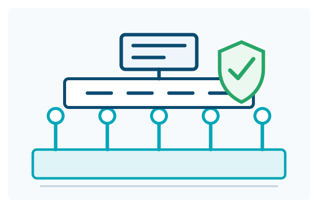
Platform and application landing zone layers

A landing zone is the structured cloud foundation that defines how your organization operates on STACKIT from day 1. It combines governance, identity, security, network design, cost controls, and automation into one coherent baseline.

Without this foundation, migration waves typically stall due to missing approvals, inconsistent controls, and repeated platform decisions.

The following visual summarizes the core components that should be addressed for a reliable platform baseline.

Landing zone core components Six building blocks of a secure landing zone. Landing zone core componentsThe six building blocks of a secure platform foundation on STACKIT.Account GovernanceAccount GovernanceHow do I structure my projects?Identity & Access ManagementIdentity & Access ManagementWho can do what on the platform?Security & ComplianceSecurity & ComplianceHow do I monitor and protect?Network ArchitectureNetwork ArchitectureHow are components securely connected?Cost Management and ControlCost Management and ControlHow do I keep spending in control?Automation (IaC)Automation (IaC)How is everything delivered and managed?
  • Control and risk reduction: Enforce security and compliance controls consistently across teams.
  • Scalable delivery baseline: Enable repeatable provisioning patterns for multiple migration waves.
  • Clear responsibilities: Define ownership boundaries for platform, security, and application teams.
  • Faster migration throughput: Avoid redesigning core controls for each application move.

Start the landing-zone stream as early as possible, in parallel with discovery.

  • Too late: Productive migrations are blocked because mandatory controls are not yet available.
  • Too early without discovery feedback: Application constraints are missed and later cause rework.

The practical model is a dual track: establish the platform baseline early, then refine application landing zone templates as discovery insights mature.

Two layers: Platform and Application Landing Zones

Section titled “Two layers: Platform and Application Landing Zones”

Platform Landing Zone

Company-wide foundation for governance, identity, security, networking, cost controls, and automation.

Open Platform Landing Zone

Application Landing Zone

Workload-specific implementation patterns derived from the platform baseline and discovery findings.

Open Application Landing Zone

To design a landing zone effectively, enterprises usually provide:

  • Organization and ownership model: Entities, project boundaries, and accountability model.
  • Compliance and policy requirements: Regulatory obligations and internal control policies.
  • Security requirements: IAM standards, network segmentation, encryption, and logging expectations.
  • Operations and support constraints: Incident handling, escalation paths, and handover model.
  • Application portfolio insights: Discovery findings about workload archetypes and dependencies.
  1. Define enterprise guardrails and target control model.
  2. Build and validate the platform landing zone baseline as code.
  3. Derive application landing zone templates from discovery and migration design.
  4. Pilot with selected workloads, then scale through migration factory runbooks.

To accelerate delivery, STACKIT provides concrete best practices and reusable templates:

Asset title
Framework
Asset type

A landing zone is the structured cloud foundation that defines how your organization operates on STACKIT from day 1. It combines governance, identity, security, network design, cost controls, and automation into one coherent baseline.

Without this foundation, migration waves typically stall due to missing approvals, inconsistent controls, and repeated platform decisions.

The following visual summarizes the core components that should be addressed for a reliable platform baseline.

Landing zone core components Six building blocks of a secure landing zone. Landing zone core componentsThe six building blocks of a secure platform foundation on STACKIT.Account GovernanceAccount GovernanceHow do I structure my projects?Identity & Access ManagementIdentity & Access ManagementWho can do what on the platform?Security & ComplianceSecurity & ComplianceHow do I monitor and protect?Network ArchitectureNetwork ArchitectureHow are components securely connected?Cost Management and ControlCost Management and ControlHow do I keep spending in control?Automation (IaC)Automation (IaC)How is everything delivered and managed?
  • Control and risk reduction: Enforce security and compliance controls consistently across teams.
  • Scalable delivery baseline: Enable repeatable provisioning patterns for multiple migration waves.
  • Clear responsibilities: Define ownership boundaries for platform, security, and application teams.
  • Faster migration throughput: Avoid redesigning core controls for each application move.

Start the landing-zone stream as early as possible, in parallel with discovery.

  • Too late: Productive migrations are blocked because mandatory controls are not yet available.
  • Too early without discovery feedback: Application constraints are missed and later cause rework.

The practical model is a dual track: establish the platform baseline early, then refine application landing zone templates as discovery insights mature.

Two layers: Platform and Application Landing Zones

Section titled “Two layers: Platform and Application Landing Zones”

Platform Landing Zone

Company-wide foundation for governance, identity, security, networking, cost controls, and automation.

Open Platform Landing Zone

Application Landing Zone

Workload-specific implementation patterns derived from the platform baseline and discovery findings.

Open Application Landing Zone

To design a landing zone effectively, enterprises usually provide:

  • Organization and ownership model: Entities, project boundaries, and accountability model.
  • Compliance and policy requirements: Regulatory obligations and internal control policies.
  • Security requirements: IAM standards, network segmentation, encryption, and logging expectations.
  • Operations and support constraints: Incident handling, escalation paths, and handover model.
  • Application portfolio insights: Discovery findings about workload archetypes and dependencies.
  1. Define enterprise guardrails and target control model.
  2. Build and validate the platform landing zone baseline as code.
  3. Derive application landing zone templates from discovery and migration design.
  4. Pilot with selected workloads, then scale through migration factory runbooks.

To accelerate delivery, STACKIT provides concrete best practices and reusable templates:

Asset title
Framework
Asset type

STACKIT LogoSTACKIT Logo
STACKIT Landing Zone Accelerator STACKIT · Blueprint Open asset ↗

Architecture overview of the STACKIT Landing Zone Accelerator, from bootstrap through platform capabilities to application landing zones and workloads

This asset provides a reusable foundation for implementing a STACKIT platform landing zone. It is designed for enterprise environments that need a structured baseline for governance, security, networking, cost controls, and automation.

Repository:

This repository is a single root-module accelerator with modular submodules.

  • The root module in src/main.tf orchestrates all platform and landing-zone building blocks.
  • Configuration is provided through flavor-specific variable files in src/config/.
  • You can deploy with OpenTofu or Terraform (same module graph).
  • The initial deployment uses a temporary bootstrap service account, then migrates to a managed backend and managed credentials.

The repository provides eight reference configurations in src/config/. Choose the simplest topology that satisfies the required network, security, organizational, tenant, and regional boundaries.
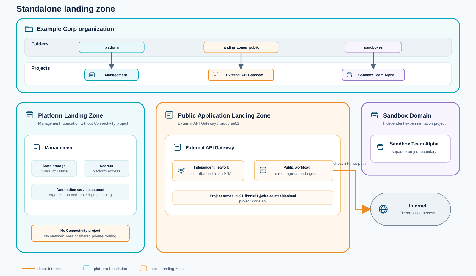
Standalone topology with a management foundation, sandbox, and public application landing zone

Use standalone.tfvars for the smallest foundation: governance, management, a sandbox, and a public application landing zone with its own network and direct internet access. It creates no shared Network Area or connectivity hub, making it suitable when workloads do not require private east-west connectivity or central DNS.
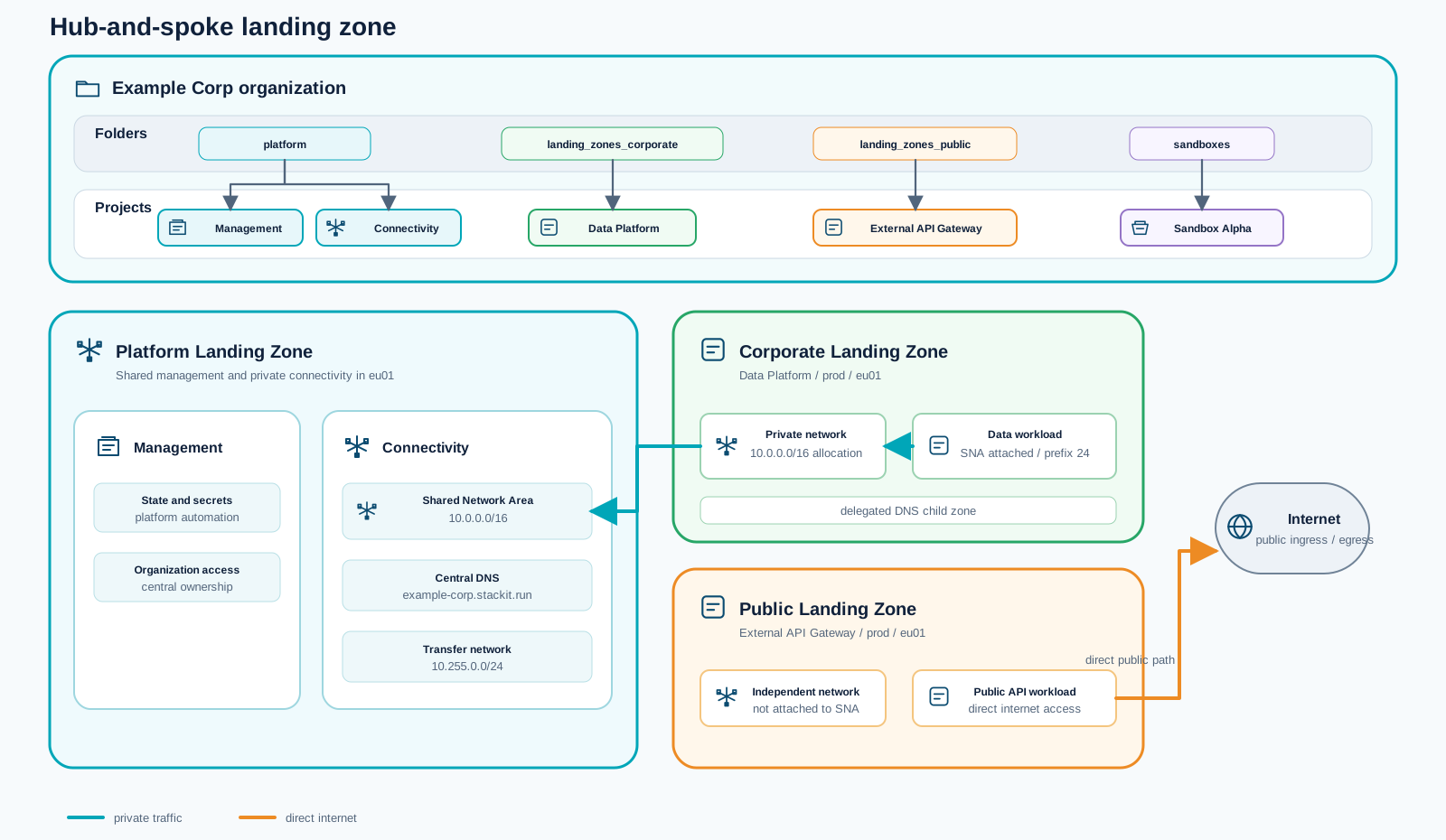
Hub-and-spoke topology with a shared Network Area and separate public landing zone

Use hub-and-spoke.tfvars when corporate workloads need shared private connectivity. A central connectivity project provides the Network Area and DNS, the corporate data platform joins that private domain, and public workloads retain independent networks with direct internet access.
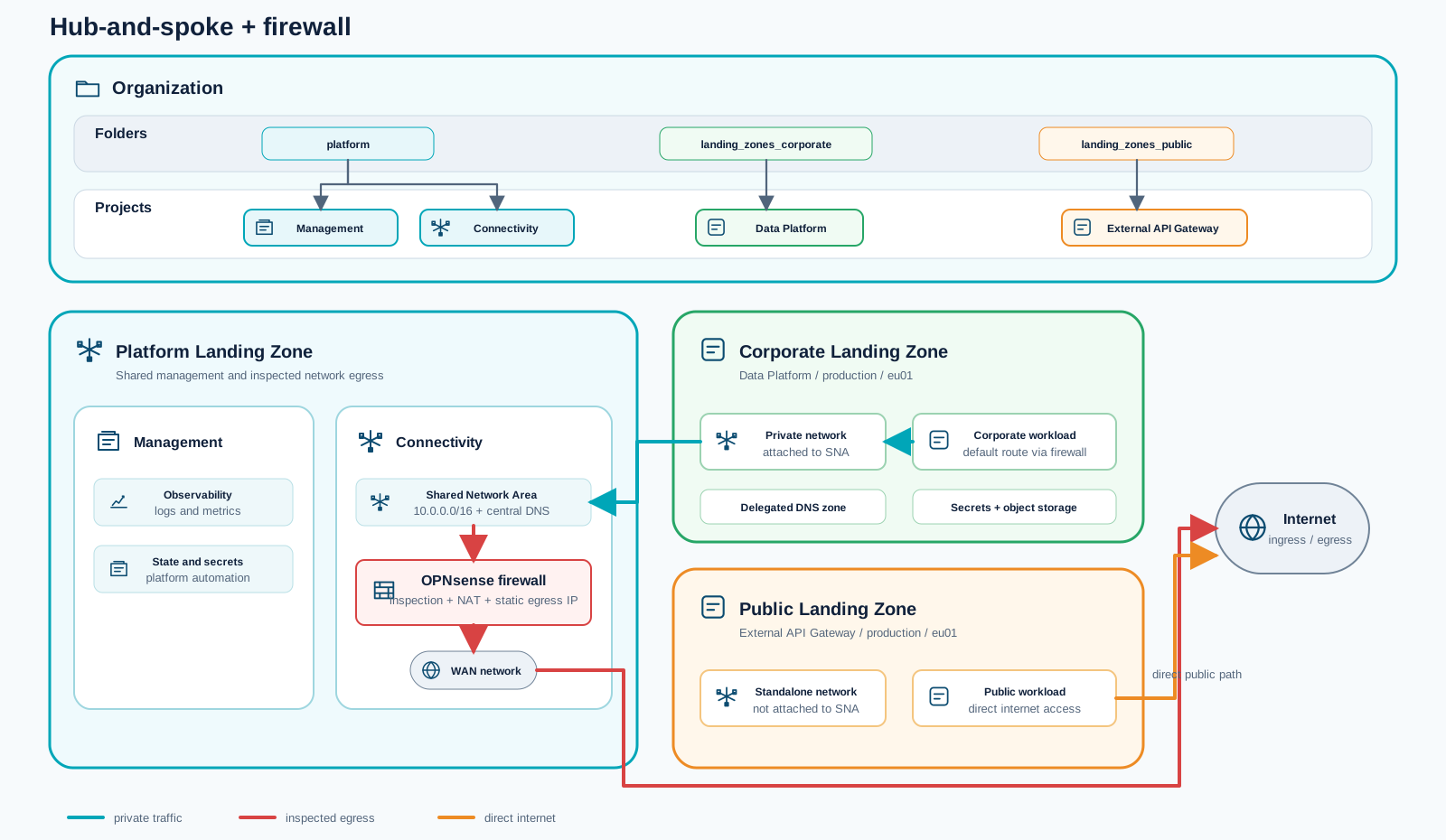
Hub-and-spoke topology with centralized OPNsense firewall inspection

Use hub-and-spoke-firewall.tfvars when corporate egress needs a consistent inspection and control point. It extends the shared Network Area with an OPNsense firewall and steers corporate default routes through the appliance, while public landing zones remain directly connected.
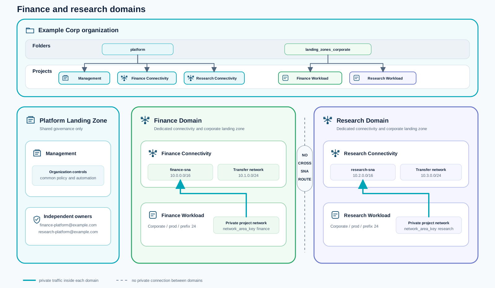
Finance and research topology with independent private connectivity domains

Use hub-and-spoke-finance-research.tfvars when business units require independent ownership and private connectivity. Finance and research each receive their own address plan, connectivity project, Network Area, and workload landing zone within the same STACKIT organization.
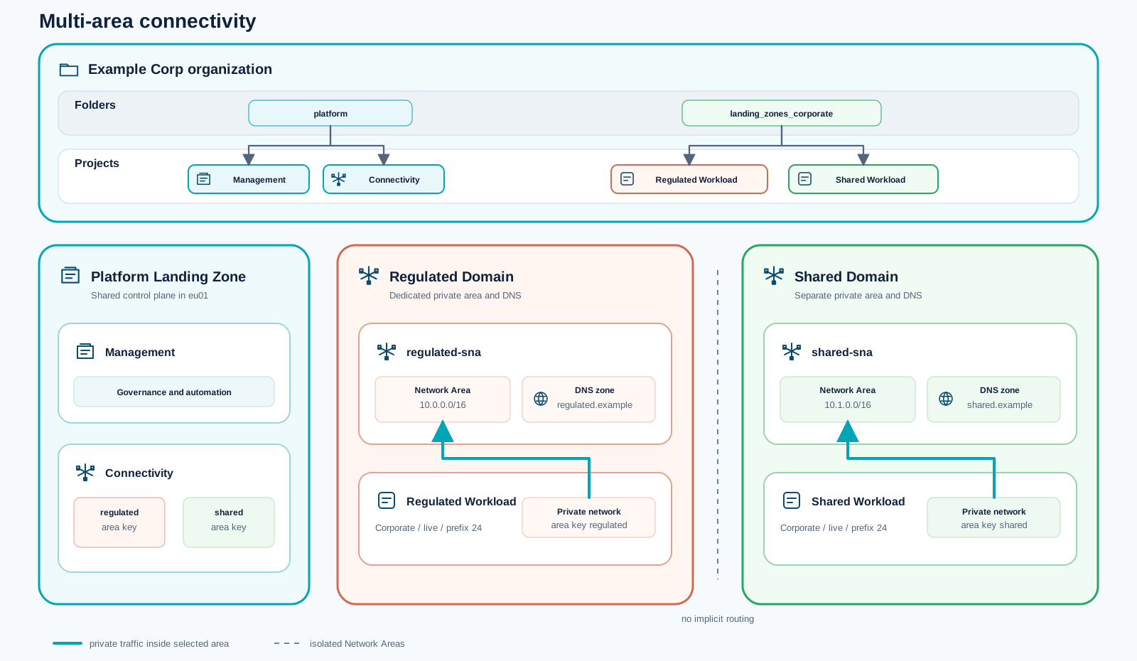
Multi-area topology separating regulated and shared workloads

Use hub-and-spoke-multi-area.tfvars when regulated and shared workloads must occupy separate private connectivity domains. Each domain has its own Network Area and DNS zone, with no implicit routing between them.
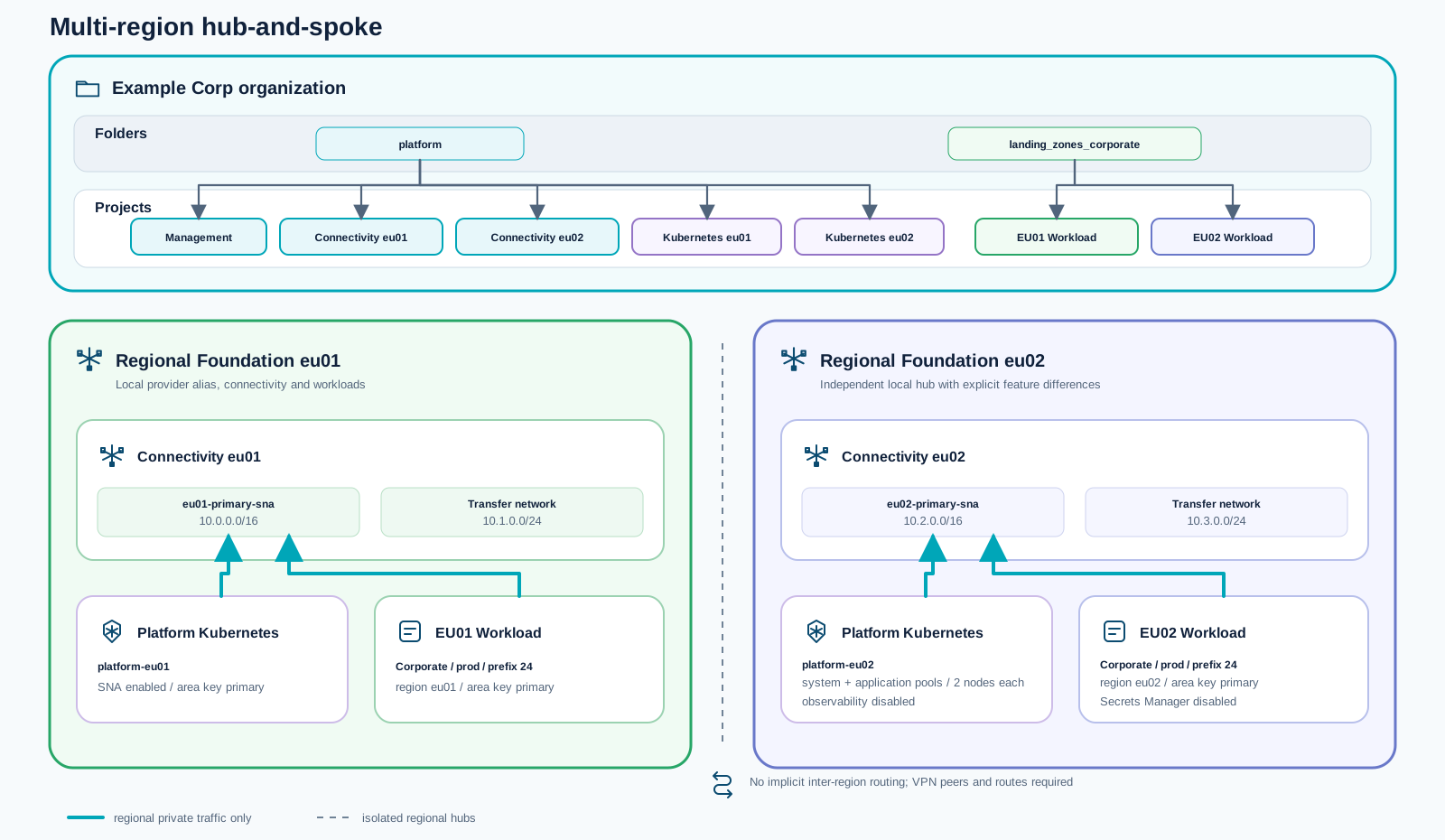
Multi-region topology with independent hubs in eu01 and eu02

Use hub-and-spoke-multi-region.tfvars for regional foundations in eu01 and eu02. Each region receives an independent hub, Network Area, workload landing zone, and optional platform Kubernetes cluster. Inter-region connectivity is deliberately not created and must be designed explicitly.
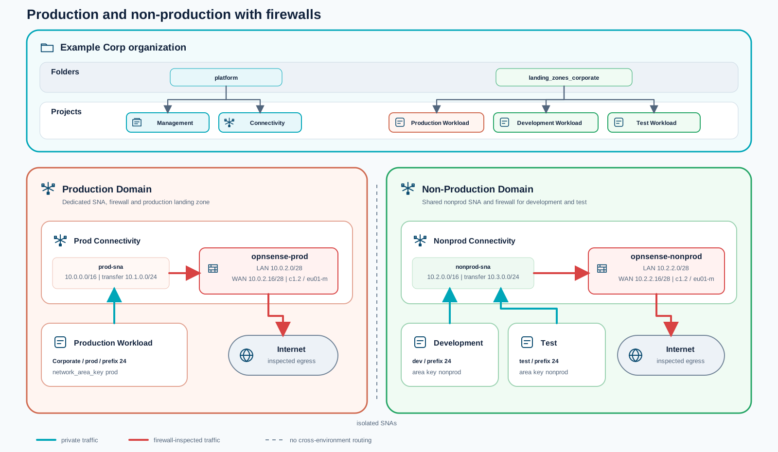
Production and non-production topology with separate Network Areas and firewalls

Use hub-and-spoke-prod-nonprod-firewall.tfvars when production must be isolated from non-production. Each domain receives a dedicated Network Area and OPNsense firewall; development and test share the non-production domain while remaining separate landing zones.
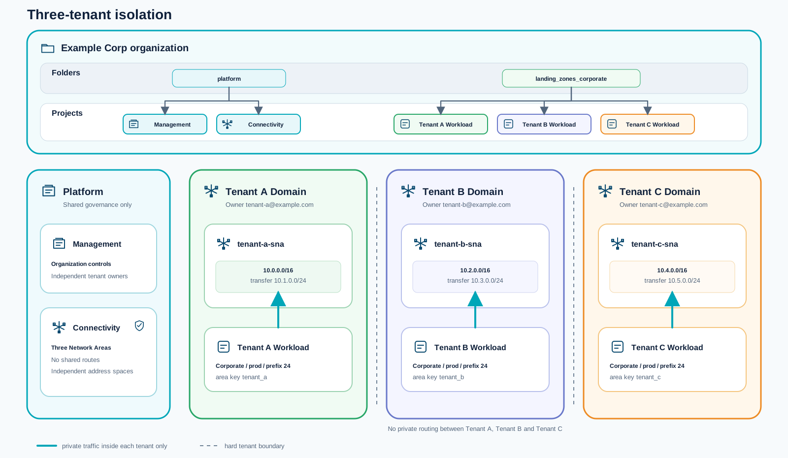
Tenant isolation topology with three independent private tenant domains

Use hub-and-spoke-tenant-isolation.tfvars for multiple tenants inside one organization. Every tenant receives an independent owner, address plan, Network Area, connectivity project, and workload landing zone, without private routing to the other tenant domains.

Code & registry github.com Landing Zone Accelerator architecture Review the implementation architecture, deployment configurations, and network behavior in the source repository. Open the repository

1. Governance module (src/modules/governance)

Section titled “1. Governance module (src/modules/governance)”

Purpose:

  • Creates RM folder structure (platform, landing_zones_corporate, landing_zones_public, sandboxes).
  • Assigns folder-level owners and auditors.
  • Assigns organization-level owners and auditors.
  • Creates custom roles at organization scope.

Landing-zone classification:

  • Platform Landing Zone: core governance baseline.

2. Management module (src/modules/management)

Section titled “2. Management module (src/modules/management)”

Purpose:

  • Creates a central management project.
  • Provisions Secrets Manager and default access user.
  • Provisions object storage buckets (including a remote state bucket).
  • Creates object-storage credentials and stores them in Secrets Manager.
  • Creates automation service account + rotating keys, stores key in Secrets Manager.
  • Optionally provisions observability and stores observability credentials in Secrets Manager.
  • Optionally configures federated identity providers for the automation service account.

Landing-zone classification:

  • Platform Landing Zone: shared operations and automation control plane.

3. Connectivity module (src/modules/connectivity)

Section titled “3. Connectivity module (src/modules/connectivity)”

Purpose:

  • Creates a dedicated connectivity project.
  • Creates network area and regional network-area configuration.
  • Creates DNS zones for shared naming domains.
  • Optionally creates firewall image, volume, server, interfaces, public IP.
  • Exposes firewall next-hop IP for route injection into corporate landing zones.

Landing-zone classification:

  • Platform Landing Zone: shared network and routing baseline.

Purpose:

  • Creates a dedicated DevOps project.
  • Optionally creates a central STACKIT Git instance with ACL ranges.

Landing-zone classification:

  • Platform Landing Zone in this accelerator’s architecture.
  • Rationale: it provides shared delivery tooling and central CI/CD source-control capability across landing zones.

5. Landing-Zone module (src/modules/landing-zone)

Section titled “5. Landing-Zone module (src/modules/landing-zone)”

Purpose:

  • Creates application-facing landing-zone projects (iterative via for_each).
  • Supports corporate landing zones (network area-connected) and public landing zones.
  • Creates routed networks, optional routing-table default route via firewall next hop.
  • Optionally creates per-project child DNS zones.
  • Creates project-level custom roles and role assignments.
  • Creates Secrets Manager, object-storage buckets, and automation service-account key material per landing zone.

Landing-zone classification:

  • Application Landing Zone: primary ALZ implementation module.

6. Sandboxes module (src/modules/sandboxes)

Section titled “6. Sandboxes module (src/modules/sandboxes)”

Purpose:

  • Creates lightweight sandbox projects in the dedicated sandboxes folder.
  • Assigns project owners.

Landing-zone classification:

  • Application Landing Zone (supporting): non-production experimentation space close to ALZ usage patterns.

The current implementation now includes an end-to-end path for a central Kubernetes platform and namespace-based application onboarding.

Platform landing zone for central Kubernetes

Section titled “Platform landing zone for central Kubernetes”

The platform scope now includes a dedicated central Kubernetes foundation that can be operated as a shared platform service.

  • Central cluster foundation: A dedicated platform Kubernetes project with SKE cluster life cycle, DNS extension integration, and optional observability wiring.
  • Secrets policy readiness: Namespace-level Secret Manager policy enforcement supports staged rollout modes such as audit and strict.
  • Shared service model: Platform teams can expose central capabilities while keeping project and namespace boundaries explicit.
  • Operational baseline: Cluster-level outputs and access information are exposed for automation and controlled platform operations.

Application landing zone for namespace tenants

Section titled “Application landing zone for namespace tenants”

Application landing zones can now consume namespace service from the central Kubernetes platform cluster.

  • Namespace onboarding: Landing-zone configuration can request namespace creation for an application team in the shared cluster.
  • Developer access path: Namespace-scoped Kubernetes users and role bindings are provided for tenant-level operations.
  • Service exposure: DNS and ingress patterns are preconfigured for application endpoints based on landing-zone and namespace context.
  • Secrets integration: Workloads can consume centrally governed secret flows while staying in namespace scope.

Extra platform features used in this setup

Section titled “Extra platform features used in this setup”
  • External DNS automation: DNS records for namespace services are managed from Kubernetes annotations and extension-zone integration.
  • Central Kubernetes monitoring: Platform observability integration includes Grafana access and metrics push wiring for cluster-level telemetry.
  • Dashboard provisioning workflow: Example dashboards are provisioned and imported for faster operational handover.
  • Encrypted volumes option: Platform module support for encrypted volume patterns helps align with stricter data-protection requirements.
  • Flexible network posture: The platform Kubernetes module supports SNA-oriented network setups for controlled enterprise connectivity.

What developers get in an application landing zone

Section titled “What developers get in an application landing zone”
  • Ready-to-use namespace: A preconfigured namespace in the central cluster instead of a full cluster-per-team model.
  • Least-privilege access: Namespace-scoped identities and permissions aligned to day-2 developer tasks.
  • Consistent endpoint model: Predictable DNS and ingress patterns for service publication.
  • Governed secret usage: Central secret governance with namespace-level consumption patterns.
  • Observability visibility: Shared metrics and dashboard views that help teams validate rollout and runtime behavior.

Platform vs application landing zone scope in this repository

Section titled “Platform vs application landing zone scope in this repository”
  • Platform Landing Zone focus (majority of implementation):
    • governance
    • management
    • connectivity
    • devops
  • Application Landing Zone scope (narrower by design):
    • landing-zone (core ALZ provisioning)
    • sandboxes (supporting ALZ-adjacent environments)

This means the repository delivers a strong platform baseline first, while ALZ capabilities are intentionally focused on project landing-zone provisioning and team sandbox enablement.

How to use this asset in migration programs

Section titled “How to use this asset in migration programs”
  • Start the platform baseline early (governance, management, connectivity, optional DevOps).
  • Define corporate vs public ALZ patterns based on connectivity and compliance needs.
  • Instantiate application landing zones with the landing-zone map in your variable files.
  • Use sandboxes for team onboarding and controlled early experiments.
  • Move state to the managed backend after first apply and switch from bootstrap credentials to managed automation credentials.
  • Reusable baseline modules: Building blocks for account/project structure, IAM, network, and controls.
  • Policy-oriented setup: Guardrails and conventions for secure and governed cloud usage.
  • IaC-first approach: OpenTofu/Terraform implementation model for repeatable provisioning.
  • Enterprise extensibility: Designed as a baseline to be adapted to customer-specific requirements.
  • Early platform stream: Start foundation setup in parallel with discovery.
  • Control baseline before production move: Ensure mandatory controls are in place before productive migrations.
  • Template source for application landing zones: Reuse and refine baseline modules for workload archetypes.
  • Organization and ownership model for projects/environments.
  • Security and compliance requirements (identity, logging, evidence, segmentation).
  • Connectivity constraints and integration requirements.
  • Operating model alignment across platform, security, and application teams.
STACKIT Landing Zone Accelerator architecture from bootstrap through platform capabilities to application landing zones
STACKIT LogoSTACKIT Logo
VM Application Landing Zone for Relocate STACKIT · Blueprint Open asset ↗

Use this blueprint to create the Application Landing Zone for a VM-based Relocate wave. It keeps the shared Platform Landing Zone, the workload project baseline, and the migrated workload clearly separated while giving Coriolis or Hystax Acura a controlled target in which to deploy.

The Platform Landing Zone supplies organization-wide governance, connectivity, identity, audit, and automation capabilities. The STACKIT Landing Zone Accelerator then creates one Application Landing Zone project for the workload and environment. Security Groups form an explicit manual approval gate before migration tooling or VMs enter that project.

Platform Landing ZoneVM Application Landing ZoneTool and workload contentGovernance and IAMShared connectivity and DNSAudit and automation baselineAccelerator baselineManual gateCoriolis or Hystax AcuraMigrated VMs and volumesGuest metrics, logs, and backupSTACKIT project and RBACRouted network and DNS zoneSecrets Manager and automation identityObject Storage and state bucketObservability endpointSecurity GroupsRule review and approval baseline readyinherit shared route policyinherit guardrailsapproved ingress and egress

The boundary is deliberate:

  • Landing Zone responsibility: Project, roles, routed network, DNS zone, Secrets Manager, Object Storage, automation identity, optional Observability instance, labels, and shared routing.
  • Manual security responsibility: Security Groups and their workload-specific ingress and egress rules are reviewed and created before tool deployment.
  • Workload responsibility: Migration appliances, migrated servers and volumes, guest configuration, application dependencies, backup policies, and telemetry agents.

Create one Accelerator landing_zones entry per workload environment. For a private VMware target, use a corporate landing zone connected to the approved Network Area and enable Observability.

landing_zones = {
"erp-prod" = {
project_name = "ERP Production"
project_code = "erp"
owner_email = "platform-owner@example.com"
env = "prod"
corporate = true
network_area_key = "default"
network_prefix_length = 24
secretsmanager_enabled = true
observability = {
enabled = true
plan_name = "Observability-Starter-EU01"
acl = ["approved-admin-cidr"]
}
role_assignments = [
{
role = "project.owner"
subject = "migration-automation@example.com"
}
]
}
}

After tofu apply, capture the project ID, landing-zone type, connected Network Area ID, DNS zone, Secrets Manager instance ID, Observability instance ID, Grafana URL, and metrics push URL. These outputs become controlled inputs for the migration wave, not values chosen during cutover.

The Accelerator does not create migrated VMs, workload disks, guest agents, or Security Groups in this module. It creates the governed project baseline into which those resources are deployed.

Create Security Groups only after the dependency matrix and tool path are approved. Keep the rule set version-controlled even when the initial creation is manual.

Review the default ingress and egress behavior before writing the approved rule set. Explicitly test same-group traffic and outbound restrictions rather than assuming every direction is denied by default. Resolve migration-tool ports from the selected tool’s documentation.

From the STACKIT docsConcepts › Security rulesSource updated 19.11.2025 · copied 06.10.2026

Security Group rules define which traffic is allowed or denied. Each rule specifies:

  • Direction: Whether the rule applies to incoming traffic (ingress) or outgoing traffic (egress)
  • IP Protocol: The network protocol (TCP, UDP, ICMP, or any protocol)
  • Port Range: The specific port or range of ports affected by the rule (for TCP/UDP)
  • Source/Destination: IP addresses or CIDR blocks that the rule applies to

Default behavior

When you create a new Security Group, it includes a default security policy:

  • Egress (Outbound): All outgoing traffic is allowed by default
  • Ingress (Inbound): All incoming traffic is blocked by default, with one important exception—traffic from instances within the same Security Group is allowed

The default deny-all ingress policy ensures that your servers remain protected until you explicitly allow specific traffic. This “deny by default” approach prevents accidental exposure of services to the internet and helps maintain a strong security posture.

Ingress rules

Ingress rules control incoming traffic to your servers. You must explicitly create ingress rules to allow:

  • External access to your applications (e.g., HTTP/HTTPS traffic on ports 80/443)
  • Management access (e.g., SSH on port 22 or RDP on port 3389)
  • Custom application traffic on specific ports
  • Traffic from specific IP addresses or ranges

Egress rules

Egress rules control outgoing traffic from your servers. By default there is a rule that allows all egress traffic. You can create restrictive egress rules to:

  • Limit outbound connections to specific destinations
  • Control which protocols and ports your servers can use for outbound communication
  • Implement security policies that restrict data exfiltration
What is this?

This section is copied from the STACKIT docs automatically, several times a day. It cannot be changed here. Changes belong in the STACKIT docs.

  1. Create separate groups for migration-tool management, transfer traffic, workload ingress, and workload east-west dependencies where their life cycles differ.
  2. Allow administration only from approved operator or bastion ranges.
  3. Allow Coriolis or Acura control and data paths only between the documented source, appliance, worker, and target addresses. Resolve exact ports from the approved product version.
  4. Translate the Discovery dependency matrix into explicit workload rules; do not clone broad VMware VLAN access.
  5. Restrict outbound traffic to required platform services, repositories, DNS, time, telemetry, backup, and application dependencies.
  6. Record owner, purpose, evidence, expiry, and rollback for every temporary migration rule.
  7. Test default-deny behavior and remove temporary transfer rules after source retention ends.

The gate passes only when platform security and the application owner approve the rules and both migration-tool connectivity and workload dependency tests succeed.

VM Application Landing Zone build sequence

Section titled “VM Application Landing Zone build sequence”
  1. Confirm the Platform Landing Zone prerequisites: governance folders, IAM model, Network Area, shared DNS, routing and firewall policy, audit path, and automation ownership.
  2. Derive one VM Application Landing Zone specification from Discovery: environment, project owner, dependency boundaries, address demand, DNS names, data classification, availability, recovery objectives, and telemetry requirements.
  3. Add the workload environment to the Accelerator landing_zones map and enable corporate networking, Secrets Manager, and Observability as required.
  4. Apply the Accelerator and verify the project, role assignments, routed network, route policy, DNS zone, secrets boundary, state storage, automation identity, and Observability outputs.
  5. Create and approve the Security Groups manually from the dependency matrix and the selected migration tool’s control and transfer paths.
  6. Hand the approved project ID, network, DNS, Secrets Manager, Observability endpoints, Security Groups, quotas, and target mappings to either the Coriolis or Acura runbook.
  7. Let the selected tool deploy only its required appliance, worker, server, volume, image, and migration content into the Application Landing Zone.
  8. Connect VM guest metrics and logs to the provisioned Observability endpoint, apply backup and recovery policies, and validate all controls in an isolated test migration.

Do not hand the project to a migration tool before steps 1 through 5 pass. The tool consumes the Landing Zone; it does not define or replace it.

Provide the same approved Landing Zone contract to either tool while keeping their implementations separate.

  • Common inputs: STACKIT project and region, target network and addresses, Security Groups, DNS, machine and volume mappings, Secrets Manager usage, Observability endpoints, quotas, and rollback boundaries.
  • Coriolis content: Coriolis appliance components, STACKIT endpoint, minion pools, Transfers, Deployments, and the resulting VM and volume resources.
  • Hystax Acura content: Acura control components, replication integration, cloud-site settings, orchestration plans, target snapshots or volumes, and the resulting VM resources.
  • Common completion evidence: Security-rule test, dependency test, guest telemetry, backup and restore evidence, application acceptance, and removal plan for temporary migration access.

The VM Application Landing Zone is ready for a production wave when:

  • the Accelerator apply is reproducible and its outputs are stored with the wave evidence;
  • project ownership, automation identity, quotas, naming, and labels are approved;
  • network attachment, routing, DNS, and hybrid reachability are tested;
  • Secrets Manager and Observability access are restricted and operational;
  • Security Groups are manually created, reviewed, tested, and linked to the dependency matrix;
  • the selected tool can reach only its required endpoints and target resources;
  • backup, recovery, guest telemetry, acceptance thresholds, and rollback are defined.
Code & registry github.com STACKIT Landing Zone Accelerator Open the repository
STACKIT LogoSTACKIT Logo
VM Application Landing Zone for Relocate STACKIT · Blueprint Open asset ↗

Use this blueprint to create the Application Landing Zone for a VM-based Relocate wave. It keeps the shared Platform Landing Zone, the workload project baseline, and the migrated workload clearly separated while giving Coriolis or Hystax Acura a controlled target in which to deploy.

The Platform Landing Zone supplies organization-wide governance, connectivity, identity, audit, and automation capabilities. The STACKIT Landing Zone Accelerator then creates one Application Landing Zone project for the workload and environment. Security Groups form an explicit manual approval gate before migration tooling or VMs enter that project.

Platform Landing ZoneVM Application Landing ZoneTool and workload contentGovernance and IAMShared connectivity and DNSAudit and automation baselineAccelerator baselineManual gateCoriolis or Hystax AcuraMigrated VMs and volumesGuest metrics, logs, and backupSTACKIT project and RBACRouted network and DNS zoneSecrets Manager and automation identityObject Storage and state bucketObservability endpointSecurity GroupsRule review and approval baseline readyinherit shared route policyinherit guardrailsapproved ingress and egress

The boundary is deliberate:

  • Landing Zone responsibility: Project, roles, routed network, DNS zone, Secrets Manager, Object Storage, automation identity, optional Observability instance, labels, and shared routing.
  • Manual security responsibility: Security Groups and their workload-specific ingress and egress rules are reviewed and created before tool deployment.
  • Workload responsibility: Migration appliances, migrated servers and volumes, guest configuration, application dependencies, backup policies, and telemetry agents.

Create one Accelerator landing_zones entry per workload environment. For a private VMware target, use a corporate landing zone connected to the approved Network Area and enable Observability.

landing_zones = {
"erp-prod" = {
project_name = "ERP Production"
project_code = "erp"
owner_email = "platform-owner@example.com"
env = "prod"
corporate = true
network_area_key = "default"
network_prefix_length = 24
secretsmanager_enabled = true
observability = {
enabled = true
plan_name = "Observability-Starter-EU01"
acl = ["approved-admin-cidr"]
}
role_assignments = [
{
role = "project.owner"
subject = "migration-automation@example.com"
}
]
}
}

After tofu apply, capture the project ID, landing-zone type, connected Network Area ID, DNS zone, Secrets Manager instance ID, Observability instance ID, Grafana URL, and metrics push URL. These outputs become controlled inputs for the migration wave, not values chosen during cutover.

The Accelerator does not create migrated VMs, workload disks, guest agents, or Security Groups in this module. It creates the governed project baseline into which those resources are deployed.

Create Security Groups only after the dependency matrix and tool path are approved. Keep the rule set version-controlled even when the initial creation is manual.

Review the default ingress and egress behavior before writing the approved rule set. Explicitly test same-group traffic and outbound restrictions rather than assuming every direction is denied by default. Resolve migration-tool ports from the selected tool’s documentation.

From the STACKIT docsConcepts › Security rulesSource updated 19.11.2025 · copied 06.10.2026

Security Group rules define which traffic is allowed or denied. Each rule specifies:

  • Direction: Whether the rule applies to incoming traffic (ingress) or outgoing traffic (egress)
  • IP Protocol: The network protocol (TCP, UDP, ICMP, or any protocol)
  • Port Range: The specific port or range of ports affected by the rule (for TCP/UDP)
  • Source/Destination: IP addresses or CIDR blocks that the rule applies to

Default behavior

When you create a new Security Group, it includes a default security policy:

  • Egress (Outbound): All outgoing traffic is allowed by default
  • Ingress (Inbound): All incoming traffic is blocked by default, with one important exception—traffic from instances within the same Security Group is allowed

The default deny-all ingress policy ensures that your servers remain protected until you explicitly allow specific traffic. This “deny by default” approach prevents accidental exposure of services to the internet and helps maintain a strong security posture.

Ingress rules

Ingress rules control incoming traffic to your servers. You must explicitly create ingress rules to allow:

  • External access to your applications (e.g., HTTP/HTTPS traffic on ports 80/443)
  • Management access (e.g., SSH on port 22 or RDP on port 3389)
  • Custom application traffic on specific ports
  • Traffic from specific IP addresses or ranges

Egress rules

Egress rules control outgoing traffic from your servers. By default there is a rule that allows all egress traffic. You can create restrictive egress rules to:

  • Limit outbound connections to specific destinations
  • Control which protocols and ports your servers can use for outbound communication
  • Implement security policies that restrict data exfiltration
What is this?

This section is copied from the STACKIT docs automatically, several times a day. It cannot be changed here. Changes belong in the STACKIT docs.

  1. Create separate groups for migration-tool management, transfer traffic, workload ingress, and workload east-west dependencies where their life cycles differ.
  2. Allow administration only from approved operator or bastion ranges.
  3. Allow Coriolis or Acura control and data paths only between the documented source, appliance, worker, and target addresses. Resolve exact ports from the approved product version.
  4. Translate the Discovery dependency matrix into explicit workload rules; do not clone broad VMware VLAN access.
  5. Restrict outbound traffic to required platform services, repositories, DNS, time, telemetry, backup, and application dependencies.
  6. Record owner, purpose, evidence, expiry, and rollback for every temporary migration rule.
  7. Test default-deny behavior and remove temporary transfer rules after source retention ends.

The gate passes only when platform security and the application owner approve the rules and both migration-tool connectivity and workload dependency tests succeed.

VM Application Landing Zone build sequence

Section titled “VM Application Landing Zone build sequence”
  1. Confirm the Platform Landing Zone prerequisites: governance folders, IAM model, Network Area, shared DNS, routing and firewall policy, audit path, and automation ownership.
  2. Derive one VM Application Landing Zone specification from Discovery: environment, project owner, dependency boundaries, address demand, DNS names, data classification, availability, recovery objectives, and telemetry requirements.
  3. Add the workload environment to the Accelerator landing_zones map and enable corporate networking, Secrets Manager, and Observability as required.
  4. Apply the Accelerator and verify the project, role assignments, routed network, route policy, DNS zone, secrets boundary, state storage, automation identity, and Observability outputs.
  5. Create and approve the Security Groups manually from the dependency matrix and the selected migration tool’s control and transfer paths.
  6. Hand the approved project ID, network, DNS, Secrets Manager, Observability endpoints, Security Groups, quotas, and target mappings to either the Coriolis or Acura runbook.
  7. Let the selected tool deploy only its required appliance, worker, server, volume, image, and migration content into the Application Landing Zone.
  8. Connect VM guest metrics and logs to the provisioned Observability endpoint, apply backup and recovery policies, and validate all controls in an isolated test migration.

Do not hand the project to a migration tool before steps 1 through 5 pass. The tool consumes the Landing Zone; it does not define or replace it.

Provide the same approved Landing Zone contract to either tool while keeping their implementations separate.

  • Common inputs: STACKIT project and region, target network and addresses, Security Groups, DNS, machine and volume mappings, Secrets Manager usage, Observability endpoints, quotas, and rollback boundaries.
  • Coriolis content: Coriolis appliance components, STACKIT endpoint, minion pools, Transfers, Deployments, and the resulting VM and volume resources.
  • Hystax Acura content: Acura control components, replication integration, cloud-site settings, orchestration plans, target snapshots or volumes, and the resulting VM resources.
  • Common completion evidence: Security-rule test, dependency test, guest telemetry, backup and restore evidence, application acceptance, and removal plan for temporary migration access.

The VM Application Landing Zone is ready for a production wave when:

  • the Accelerator apply is reproducible and its outputs are stored with the wave evidence;
  • project ownership, automation identity, quotas, naming, and labels are approved;
  • network attachment, routing, DNS, and hybrid reachability are tested;
  • Secrets Manager and Observability access are restricted and operational;
  • Security Groups are manually created, reviewed, tested, and linked to the dependency matrix;
  • the selected tool can reach only its required endpoints and target resources;
  • backup, recovery, guest telemetry, acceptance thresholds, and rollback are defined.
Code & registry github.com STACKIT Landing Zone Accelerator Open the repository
STACKIT LogoSTACKIT Logo
VM Application Landing Zone for Relocate STACKIT · Blueprint Open asset ↗

Use this blueprint to create the Application Landing Zone for a VM-based Relocate wave. It keeps the shared Platform Landing Zone, the workload project baseline, and the migrated workload clearly separated while giving Coriolis or Hystax Acura a controlled target in which to deploy.

The Platform Landing Zone supplies organization-wide governance, connectivity, identity, audit, and automation capabilities. The STACKIT Landing Zone Accelerator then creates one Application Landing Zone project for the workload and environment. Security Groups form an explicit manual approval gate before migration tooling or VMs enter that project.

Platform Landing ZoneVM Application Landing ZoneTool and workload contentGovernance and IAMShared connectivity and DNSAudit and automation baselineAccelerator baselineManual gateCoriolis or Hystax AcuraMigrated VMs and volumesGuest metrics, logs, and backupSTACKIT project and RBACRouted network and DNS zoneSecrets Manager and automation identityObject Storage and state bucketObservability endpointSecurity GroupsRule review and approval baseline readyinherit shared route policyinherit guardrailsapproved ingress and egress

The boundary is deliberate:

  • Landing Zone responsibility: Project, roles, routed network, DNS zone, Secrets Manager, Object Storage, automation identity, optional Observability instance, labels, and shared routing.
  • Manual security responsibility: Security Groups and their workload-specific ingress and egress rules are reviewed and created before tool deployment.
  • Workload responsibility: Migration appliances, migrated servers and volumes, guest configuration, application dependencies, backup policies, and telemetry agents.

Create one Accelerator landing_zones entry per workload environment. For a private VMware target, use a corporate landing zone connected to the approved Network Area and enable Observability.

landing_zones = {
"erp-prod" = {
project_name = "ERP Production"
project_code = "erp"
owner_email = "platform-owner@example.com"
env = "prod"
corporate = true
network_area_key = "default"
network_prefix_length = 24
secretsmanager_enabled = true
observability = {
enabled = true
plan_name = "Observability-Starter-EU01"
acl = ["approved-admin-cidr"]
}
role_assignments = [
{
role = "project.owner"
subject = "migration-automation@example.com"
}
]
}
}

After tofu apply, capture the project ID, landing-zone type, connected Network Area ID, DNS zone, Secrets Manager instance ID, Observability instance ID, Grafana URL, and metrics push URL. These outputs become controlled inputs for the migration wave, not values chosen during cutover.

The Accelerator does not create migrated VMs, workload disks, guest agents, or Security Groups in this module. It creates the governed project baseline into which those resources are deployed.

Create Security Groups only after the dependency matrix and tool path are approved. Keep the rule set version-controlled even when the initial creation is manual.

Review the default ingress and egress behavior before writing the approved rule set. Explicitly test same-group traffic and outbound restrictions rather than assuming every direction is denied by default. Resolve migration-tool ports from the selected tool’s documentation.

From the STACKIT docsConcepts › Security rulesSource updated 19.11.2025 · copied 06.10.2026

Security Group rules define which traffic is allowed or denied. Each rule specifies:

  • Direction: Whether the rule applies to incoming traffic (ingress) or outgoing traffic (egress)
  • IP Protocol: The network protocol (TCP, UDP, ICMP, or any protocol)
  • Port Range: The specific port or range of ports affected by the rule (for TCP/UDP)
  • Source/Destination: IP addresses or CIDR blocks that the rule applies to

Default behavior

When you create a new Security Group, it includes a default security policy:

  • Egress (Outbound): All outgoing traffic is allowed by default
  • Ingress (Inbound): All incoming traffic is blocked by default, with one important exception—traffic from instances within the same Security Group is allowed

The default deny-all ingress policy ensures that your servers remain protected until you explicitly allow specific traffic. This “deny by default” approach prevents accidental exposure of services to the internet and helps maintain a strong security posture.

Ingress rules

Ingress rules control incoming traffic to your servers. You must explicitly create ingress rules to allow:

  • External access to your applications (e.g., HTTP/HTTPS traffic on ports 80/443)
  • Management access (e.g., SSH on port 22 or RDP on port 3389)
  • Custom application traffic on specific ports
  • Traffic from specific IP addresses or ranges

Egress rules

Egress rules control outgoing traffic from your servers. By default there is a rule that allows all egress traffic. You can create restrictive egress rules to:

  • Limit outbound connections to specific destinations
  • Control which protocols and ports your servers can use for outbound communication
  • Implement security policies that restrict data exfiltration
What is this?

This section is copied from the STACKIT docs automatically, several times a day. It cannot be changed here. Changes belong in the STACKIT docs.

  1. Create separate groups for migration-tool management, transfer traffic, workload ingress, and workload east-west dependencies where their life cycles differ.
  2. Allow administration only from approved operator or bastion ranges.
  3. Allow Coriolis or Acura control and data paths only between the documented source, appliance, worker, and target addresses. Resolve exact ports from the approved product version.
  4. Translate the Discovery dependency matrix into explicit workload rules; do not clone broad VMware VLAN access.
  5. Restrict outbound traffic to required platform services, repositories, DNS, time, telemetry, backup, and application dependencies.
  6. Record owner, purpose, evidence, expiry, and rollback for every temporary migration rule.
  7. Test default-deny behavior and remove temporary transfer rules after source retention ends.

The gate passes only when platform security and the application owner approve the rules and both migration-tool connectivity and workload dependency tests succeed.

VM Application Landing Zone build sequence

Section titled “VM Application Landing Zone build sequence”
  1. Confirm the Platform Landing Zone prerequisites: governance folders, IAM model, Network Area, shared DNS, routing and firewall policy, audit path, and automation ownership.
  2. Derive one VM Application Landing Zone specification from Discovery: environment, project owner, dependency boundaries, address demand, DNS names, data classification, availability, recovery objectives, and telemetry requirements.
  3. Add the workload environment to the Accelerator landing_zones map and enable corporate networking, Secrets Manager, and Observability as required.
  4. Apply the Accelerator and verify the project, role assignments, routed network, route policy, DNS zone, secrets boundary, state storage, automation identity, and Observability outputs.
  5. Create and approve the Security Groups manually from the dependency matrix and the selected migration tool’s control and transfer paths.
  6. Hand the approved project ID, network, DNS, Secrets Manager, Observability endpoints, Security Groups, quotas, and target mappings to either the Coriolis or Acura runbook.
  7. Let the selected tool deploy only its required appliance, worker, server, volume, image, and migration content into the Application Landing Zone.
  8. Connect VM guest metrics and logs to the provisioned Observability endpoint, apply backup and recovery policies, and validate all controls in an isolated test migration.

Do not hand the project to a migration tool before steps 1 through 5 pass. The tool consumes the Landing Zone; it does not define or replace it.

Provide the same approved Landing Zone contract to either tool while keeping their implementations separate.

  • Common inputs: STACKIT project and region, target network and addresses, Security Groups, DNS, machine and volume mappings, Secrets Manager usage, Observability endpoints, quotas, and rollback boundaries.
  • Coriolis content: Coriolis appliance components, STACKIT endpoint, minion pools, Transfers, Deployments, and the resulting VM and volume resources.
  • Hystax Acura content: Acura control components, replication integration, cloud-site settings, orchestration plans, target snapshots or volumes, and the resulting VM resources.
  • Common completion evidence: Security-rule test, dependency test, guest telemetry, backup and restore evidence, application acceptance, and removal plan for temporary migration access.

The VM Application Landing Zone is ready for a production wave when:

  • the Accelerator apply is reproducible and its outputs are stored with the wave evidence;
  • project ownership, automation identity, quotas, naming, and labels are approved;
  • network attachment, routing, DNS, and hybrid reachability are tested;
  • Secrets Manager and Observability access are restricted and operational;
  • Security Groups are manually created, reviewed, tested, and linked to the dependency matrix;
  • the selected tool can reach only its required endpoints and target resources;
  • backup, recovery, guest telemetry, acceptance thresholds, and rollback are defined.
Code & registry github.com STACKIT Landing Zone Accelerator Open the repository
OPS

Migration Plan

Group VMs by verified dependencies and technical constraints, begin with a representative low-risk pilot, and define ordered runbooks, maintenance windows, cutover gates, and rollback boundaries.
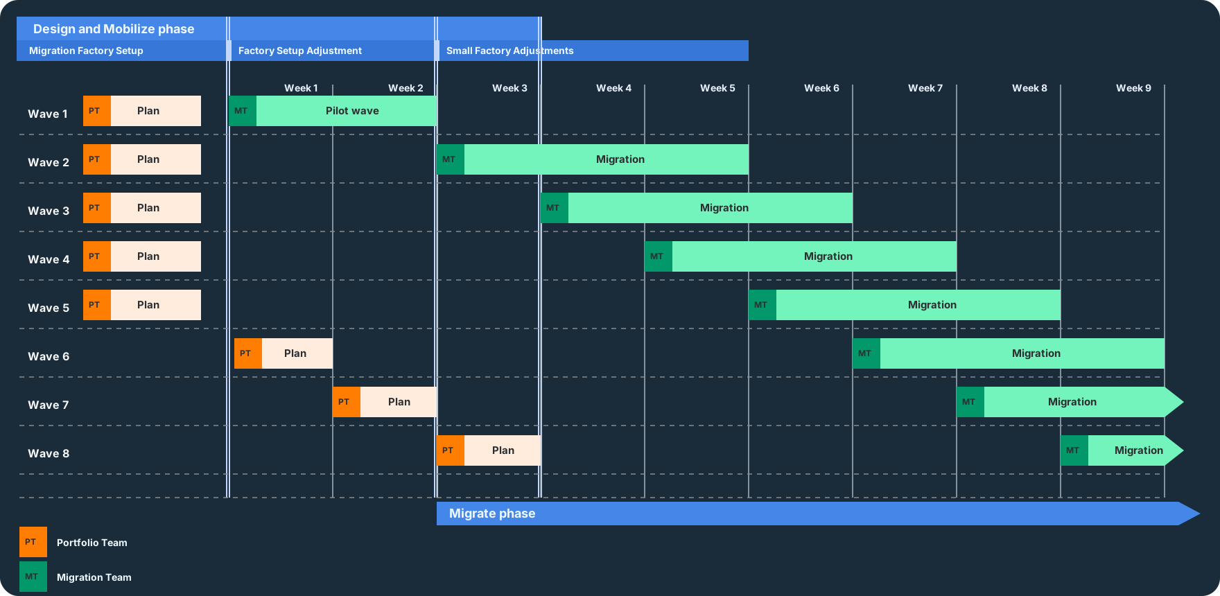
Design and mobilizeMigration planOverview In 2 trails
Migration Plan model connecting portfolio evidence, wave governance, runbooks, and controlled execution

Migration Plan is the transition from analysis to delivery. It follows Discovery and is continuously filled with concrete implementation detail from the Design module.

The goal is to transform findings from Discovery and Design into a detailed, step-by-step migration plan that delivery teams can run with predictable quality.

This module forms the bridge between strategy and implementation and is therefore critical for the overall migration success.

Wave planning

Group applications into logical migration waves based on dependency constraints, business criticality, and technical complexity.

Migration runbooks

Create detailed, step-by-step runbooks per wave or application covering preparation, delivery, cutover, rollback, and post-migration validation.

Resource planning

Define required teams, skills, tools, and expert allocation per wave, including enablement and training planning.

Delivery governance

Establish clear governance processes, ownership, communication cadence, and cutover controls for wave delivery.

Migration planning must stay adaptive. Programs should start initial waves as early as possible and then continuously refine wave scope and sequencing as additional Discovery and Design outputs become available.

Runbooks are living documents. Teams should review and improve runbooks after every cutover. As runbook quality increases, migration velocity typically increases wave by wave.

In large migration programs, the goal is to scale delivery from initial pilot waves to predictable factory throughput. A typical trajectory is to start with small waves (for example, 5 servers/week) and gradually increase throughput (for example, up to 50-100 servers/week), depending on constraints and delivery maturity.

Early waves are intentionally smaller so portfolio and migration workstreams can stabilize their processes, validate assumptions, and improve runbooks. This learning loop is a key success factor for large migrations.

In this module, the migration factory is typically operated through four components:

Project governance rules

Processes and tools that govern wave orchestration, communication, timelines, and cutovers so teams run tasks in the right sequence and at the right time.

Portfolio runbooks

Runbooks used to prioritize applications, plan waves, and collect migration metadata as the input material for delivery.

Migration runbooks

Runbooks used to run migration waves, load metadata into migration tooling, and complete cutover and validation.

Best practices and health-check matrix

A regular health-check mechanism used to assess progress, identify delivery risks early, and keep delivery on track.

Data Flow Through Portfolio and Migration Workstreams

Section titled “Data Flow Through Portfolio and Migration Workstreams”

Runbooks create the data flow across two connected workstreams:

  • Portfolio workstream: Prioritizes and prepares applications and metadata for upcoming waves.
  • Migration workstream: Runs migrations and cutovers according to approved wave plans.

Teams are usually dedicated to parts of the factory while waves flow through both workstreams. To prevent supply issues, keep enough prepared waves in front of delivery. A common baseline is to keep the portfolio workstream five waves ahead of the migration workstream.

For governance and capacity planning, it is important to separate function from team ownership:

  • Portfolio: Functional and technical wave preparation, including prioritization, dependency clarification, scope shaping, metadata quality, and readiness proof.
  • Portfolio Team: Roles that run and own portfolio work (for example, program leadership, domain owners, architects, application owners, and governance).
  • Migration: Operational delivery of approved waves, including runbook-driven delivery, change/cutover control, validation, stabilization, and documented closure.
  • Migration Team: Roles that run and secure technical migration delivery (for example, factory engineers, platform teams, network/security specialists, test, and operations handover).

Both teams are tightly coupled, but they deliver different outputs:

  • Portfolio Team delivers: Approved wave cuts, prioritized backlogs, complete migration metadata, and delivery-ready input packages.
  • Migration Team delivers: Successful cutovers, validated target states, lessons learned, and improved runbook versions for upcoming waves.

A typical dynamic pattern is:

  • Portfolio cadence: About 1-2 weeks per wave for preparation.
  • Migration cadence: About 3-4 weeks per wave for delivery and cutover.
  • Wave buffer: A five-wave buffer between portfolio and migration workstreams.

Before migration delivery reaches steady throughput, portfolio planning usually establishes an initial wave buffer. Once delivery starts, both workstreams continue in parallel and the buffer helps prevent delivery stalls.

The following diagram visualizes the operating model based on phases and modules: planning remains anchored in the Migration Plan module (Design and Mobilize), while delivery runs in staggered migration waves.

In this model, phase boundaries are intentionally overlapping:

  • Design and Mobilize starts with wave planning and remains active through the planning of Wave 8 (up to Week 3).
  • Migrate starts already in Week 3 and continues through the remaining timeline.
  • Pilot wave and adjustments: Wave 1 is a shorter pilot wave for initial validation, followed by targeted setup adjustments during the first production waves.

The detailed setup scope is documented in its dedicated chapter: Migration Factory Setup.

Swipe sideways to see the whole diagram
Wave model across phases and modules Timeline of wave-based planning and migration execution with Portfolio Team and Migration Team handover pattern. Design and Mobilize phase Migrate phase Migration Factory Setup Factory Setup Adjustment Small Factory Adjustments Week 1 Week 2 Week 3 Week 4 Week 5 Week 6 Week 7 Week 8 Week 9 Wave 1 Wave 2 Wave 3 Wave 4 Wave 5 Wave 6 Wave 7 Wave 8 PT Plan PT Plan PT Plan PT Plan PT Plan PT Plan PT Plan PT Plan MT Pilot wave MT Migration MT Migration MT Migration MT Migration MT Migration MT Migration MT Migration PT Portfolio Team MT Migration Team

The pattern is intentionally dynamic: portfolio work keeps a stable forward buffer, while migration work runs waves with runbooks, cutovers, and validation.

Migration Factory Process in the Module Flow

Section titled “Migration Factory Process in the Module Flow”

Migration Plan connects Discovery and Design outputs with delivery governance, wave planning, and runbook-driven delivery. The process tightly links portfolio and migration workstreams through governance controls, runbooks, and continuous improvement.

Wave planning is not a static schedule. It is an operational timeline that must remain transparent for stakeholders and adaptable to new findings. Cadence, overlap between workstreams, and buffer logic are the key control variables.

  1. Confirm latest Discovery and Design inputs, constraints, and assumptions.
  2. Update wave composition, sequencing, and staffing based on current facts.
  3. Run the current wave with approved migration and cutover runbooks.
  4. Review cutover outcomes, incidents, and timing variances.
  5. Improve governance controls and runbooks, then apply updates to upcoming waves.
  6. Re-check health status and wave buffer, then continue with the next iteration.

At minimum, Migration Plan should produce:

  • Approved wave plan: Sequenced migration waves with dependency-aware grouping.
  • Executable runbooks: Versioned runbooks per wave/application with validation and rollback.
  • Resource and skill plan: Staffing and capability mapping per wave.
  • Governance cadence: Decision, communication, and cutover control framework.
  • Continuous improvement backlog: Tracked runbook and process improvements from each wave.
STACKIT LogoSTACKIT Logo
VMware Relocate Wave Execution STACKIT · Runbook Open asset ↗

Use this runbook to execute one approved VMware Relocate wave to STACKIT. It provides two complete tool paths: Cloudbase Coriolis and Hystax Acura. Select one path for the entire wave and retain the same tool, inventory identifiers, mappings, and evidence through test migration and final cutover.

The runbook assumes that applications remain VM-based. Architecture modernization, database replatforming, and application refactoring require separate plans and acceptance criteria.

Do not start replication until all entry criteria have passed:

  • Wave scope and dependency groups are frozen and every VM has a stable source identifier.
  • VMware source readiness, tool-specific prerequisites, and recovery points are verified.
  • Target machine types, volumes, performance classes, networks, addresses, security groups, and placement are approved and available within quota.
  • Application-level consistency, test cases, maintenance window, expected downtime, and maximum cutover duration are documented.
  • Source freeze, traffic switch, monitoring activation, and rollback actions have named technical owners.
  • The source retention period and the authority to delete source VMs are defined before cutover.

Create one version-controlled control record for the wave. Include:

  • source and target VM, disk, network, address, and security-group mappings;
  • selected tool and appliance or service version;
  • initial-copy start, latest successful delta, and measured replication lag;
  • ordered application shutdown and startup procedures;
  • technical and functional test cases with objective pass criteria;
  • cutover timeline, checkpoints, hold points, and decision authority;
  • rollback trigger, latest safe decision time, data reconciliation method, and source retention;
  • links to logs, screenshots, checksums, test results, and approvals.

Run the procedure first with a low-risk pilot that represents the intended operating-system, disk, network, and application patterns. Promote the runbook to larger waves only after pilot findings are incorporated.

Select this complete path when Cloudbase Coriolis is the approved migration tool.

  1. Run the Coriolis STACKIT Installer dry run and cloud check against the approved project, region, machine type, storage performance class, network, DNS, and TLS configuration.
  2. Deploy the licensed appliance, store its structured result and generated credentials securely, and rerun the installer to verify that it reuses the intended resources.
  3. Verify appliance backup, administrative access, TLS, time synchronization, monitoring, quota, and the migration data paths that are not covered by the HTTPS user interface.
  1. Create the VMware source endpoint and STACKIT destination endpoint with dedicated credentials. Test authentication, certificate trust, inventory discovery, and API access independently.
  2. Configure the source and destination minion pools that execute Coriolis operations. Verify worker health, capacity, concurrency limits, routing, name resolution, and access to both endpoints.
  3. Confirm that a worker can reach every required management and data-transfer service. Browser access to the Coriolis appliance alone does not prove endpoint-to-endpoint transfer readiness.
  4. Record endpoint and minion-pool identities and versions in the wave control record so retries and cutover use the same execution topology.
  1. Create one migration Transfer definition for each approved VM or consistency group. Select the source instance and resolve every source disk and network to the approved STACKIT target design.
  2. Confirm Coriolis guest support and OS-morphing behavior. Add required bootloader, storage-driver, network, or cloud-initialization remediation to the control record.
  3. Start the first Transfer execution while the source workload remains active. Monitor source snapshots, worker health, bytes transferred, throughput, destination capacity, and failures.
  4. Run subsequent Transfer executions to synchronize changed disks. Repeat until the measured delta duration fits the cutover window, then preserve the successful execution ID and its evidence.
  1. Create a Deployment definition from the approved Transfer and map the destination machine type, boot and data volumes, networks, addresses, security groups, and deployment options.
  2. Run a Deployment execution into an isolated target network without switching production traffic.
  3. Verify boot, disk discovery, file-system integrity, NIC naming, routes, DNS, NTP, certificates, and STACKIT Server Agent state. Activate Agent Service once for the destination project before using agent commands; this is separate from agent installation/provisioning on individual servers. Start dependencies and the application in the approved order.
  4. Run technical and functional tests while preventing production messages, jobs, and shared-service writes. Record defects and timing, then delete or isolate the test VM before another rehearsal.
  5. Correct the Transfer mapping, Deployment definition, or guest remediation and repeat Transfer and Deployment executions until all mandatory tests pass.
  1. Confirm the latest successful Transfer execution, current source health, target capacity, decision owners, and rollback deadline at the cutover start gate.
  2. Apply the application write freeze and stop services in the approved dependency order.
  3. Shut down the source VMs where required to prevent new writes, run the final Transfer execution, and verify its completion, transferred-disk state, and consistency evidence.
  4. Run the production Deployment execution from that Transfer. Apply only the approved production addresses, routes, security groups, DNS, and load-balancer changes.
  5. Continue with the shared validation and rollback gate. Keep the source VMs powered off and protected from automatic restart.

Select this complete path when Hystax Acura is the approved migration tool.

  1. Deploy and license the customer-isolated Acura components according to the approved STACKIT target architecture. Verify administration access, backup, time synchronization, monitoring, target storage, and target API access.
  2. Register the VMware source and STACKIT target with dedicated credentials and validate the documented management and data-transfer paths.
  3. Deploy and verify the required Hystax replication agents for the selected VMware integration. Confirm VMware Tools, Changed Block Tracking, snapshot safety, datastore headroom, and required vCenter or ESXi connectivity before protecting a VM.
  4. Freeze the source VM identifiers and target mappings used by the migration wave.
Cloud Framework Hystax Acura Live Migration Open page

Start Acura replication and store target state

Section titled “Start Acura replication and store target state”
  1. Start background replication for the approved application VMs, their disks, and required metadata. Monitor source snapshots, agent health, throughput, datastore growth, and failures.
  2. Verify that replicated data is stored as the expected volumes and snapshots in the target cloud and that retention does not exhaust target quota.
  3. Allow full and incremental replicas to complete until replication lag and the expected final delta fit the cutover window.
  4. Resolve agent, snapshot, CBT, capacity, or connectivity errors before accepting a recovery point.
  1. Create the migration plan from the approved VM, disk, network, machine-type, address, and security-group mappings.
  2. Encode dependency order and application launch sequence in the orchestration plan. Keep DNS, load-balancer, and other production traffic switches in the wave control record.
  3. Review the plan against the frozen target design and record the version selected for rehearsal.
  1. Spin up a test migration from the selected recovery point in an isolated STACKIT network without redirecting production traffic. Acura may repeat this rehearsal without stopping replication.
  2. Verify orchestrated launch order, boot, disks, file systems, NICs, routes, DNS, NTP, certificates, and STACKIT Server Agent state.
  3. Run the approved functional and performance tests while preventing production messages, jobs, and shared-service writes from the isolated target.
  4. Record defects and timing, clean up or isolate the test environment, update the migration plan, and repeat the test migration until all mandatory checks pass.
  1. Confirm the latest healthy replica, current source health, target capacity, approved migration plan, decision owners, and rollback deadline at the cutover start gate.
  2. Apply the application write freeze and stop services in the approved dependency order.
  3. Shut down the source VMs where required to prevent new writes, complete the final incremental replication, and verify the resulting recovery point.
  4. Run final cutover through the approved orchestration plan, then apply the planned production addresses, routes, security groups, DNS, and load-balancer changes.
  5. Continue with the shared validation and rollback gate. Keep the source VMs powered off and protected from automatic restart.

Start validation as soon as target instances are reachable. Record timestamps because the remaining rollback window is a technical constraint.

  1. Validate VM state: boot, console, disks, file systems, mounts, network interfaces, routes, DNS, NTP, certificates, Server Agent, and required operating-system services.
  2. Validate data state: expected recovery point, file or database consistency, checksums or record counts, and absence of unintended writes on the source.
  3. Start dependencies and applications in order, then run health checks, synthetic transactions, integrations, scheduled jobs, and mandatory business tests.
  4. Confirm logs, metrics, alerts, backups, administrative access, and security controls in the target environment.
  5. Compare CPU, memory, disk latency, IOPS, throughput, network behavior, application latency, and error rates with the approved acceptance thresholds.
  6. At the decision deadline, either accept the target or execute the documented rollback. Do not drift into an unbounded troubleshooting window.

Rollback is safe only while data ownership remains clear. If the target has accepted writes, stop target processing and execute the approved reverse synchronization or reconciliation method before the source is restarted. Never power on both copies with production connectivity unless the application design explicitly supports concurrent writers.

The wave is technically complete when:

  • mandatory technical and functional checks pass and the target is the declared system of record;
  • monitoring and backup evidence is available from STACKIT;
  • defects, temporary exceptions, and follow-up actions have owners and deadlines;
  • actual replication, freeze, cutover, and validation durations are recorded for the next wave;
  • source VMs remain powered off and access-controlled for the approved retention period;
  • source deletion occurs only after retention expiry, recovery confirmation, and explicit approval;
  • the initial target sizing is handed to Optimize with its measurements and acceptance thresholds.
LIVE

Migrate

Begin Migrate only with approved source and target states. Preserve topology assumptions, synchronize state, control traffic cutover, and require objective continuity and telemetry evidence.

MigrateMigrateOverview In 4 trails
End-to-End Migration Wave Flow Four sequential stages lead from wave approval through preparation and cutover to stabilization and handover. Every wave follows the same controlled factory flow. Secure scope and baseline, execute migration, prove acceptance, and hand over safely to operations. 1 APPROVE Scope and baseline Window, rollback, and ownership Freeze versions and dependencies 2 PREPARE Readiness and R-path Validate source and target Run playbook by archetype 3 CUT OVER Cutover and acceptance Route traffic to STACKIT safely Validate tech, function, operations 4 STABILIZE Learn and hand over Resolve findings in short loops Hand over to Optimize and Operate Traceable wave completion: accepted, stabilized, and fully handed over
Controlled migration wave flow from readiness through synchronization, cutover, validation, and handover

This module executes the actual migration delivery in the Migration Factory. By this point, design decisions are approved, landing zones are ready, and wave plans are defined.

Migrate focuses on repeatable technical run patterns for:

  • Relocate: Move workloads with minimal change in platform assumptions.
  • Rehost: Lift and shift workloads to STACKIT with controlled cutover and rollback readiness.
  • Replatform: Apply targeted platform changes during migration without a full application redesign.

Migrate starts after Design and Mobilize has produced implementable inputs:

  • Application design per workload: Target-state scope, interface decisions, data handling, and non-functional requirements are defined.
  • Wave assignment: Every workload is assigned to an approved migration wave with timing and dependency logic.
  • Runbook availability: A validated runbook exists per migration path and workload archetype, including go/no-go, cutover, and rollback criteria.
  • Application Landing Zone mapping: Workloads are mapped to the correct target landing zone and ownership model.
  • Decision and communication model: Decision paths, escalation process, and communication with the Application Owner are defined, including whether cutover must be performed jointly.

Reference modules:

  1. Confirm wave scope, cutover window, rollback criteria, and runbook ownership.
  2. Freeze wave baseline (application version, dependencies, data scope, and interface contracts).
  3. Run pre-migration technical readiness checks in source and target environments.
  4. Run migration runbook steps per workload archetype and R-strategy path.
  5. Perform cutover and route traffic to the STACKIT target according to the wave plan.
  6. Validate technical, functional, and operational acceptance criteria.
  7. Stabilize incidents and known defects in short feedback loops.
  8. Hand over stabilized workloads to Optimize and Operate.
  1. Recreate workload placement in STACKIT with equivalent topology assumptions.
  2. Migrate data and state with consistency checks.
  3. Cut over traffic with rollback guardrails.
  4. Validate business continuity and operational telemetry.
  1. Move application and data components largely unchanged.
  2. Reconfigure infrastructure bindings and connectivity on STACKIT.
  3. Run controlled cutover and smoke tests.
  4. Complete stabilization and baseline performance validation.
  1. Introduce selected managed services or platform capabilities during migration.
  2. Adapt configuration, deployment packaging, and operational controls.
  3. Cut over with compatibility and data integrity checks.
  4. Validate SLO behavior and operating model readiness.

Runbook evidence

Completed runbook records, decision logs, and rollback checkpoints for each migrated workload.

Cutover report

Time-stamped cutover outcome with acceptance results, defects, and mitigation actions.

Operational baseline

Initial monitoring, alerting, ownership, and incident procedures in the target setup.

Optimize backlog

Structured list of rightsizing, performance, and cost measures for post-cutover tuning.

Boundary to optimize, repurchase, and refactor

Section titled “Boundary to optimize, repurchase, and refactor”
  • Optimize starts directly after stable cutover and uses production telemetry to tune performance and cost: Optimize.
  • Repurchase follows a different SaaS transition logic and is treated as a dedicated module outside wave-based factory mechanics: Repurchase.
  • Refactor is typically run as a separate transformation stream: Refactor.

Post-cutover care can overlap with Optimize after cutover, but it is handled in the Run phase.

AUTO

Select and Execute One Tool Path

Choose one approved migration tool for the complete wave. Keep its endpoint, mapping, replication, test-migration, final-sync, and cutover sequence together through completion.

SAFE

Validate or Roll Back

Use this runbook to execute one approved VMware Relocate wave to STACKIT. It provides two complete tool paths: Cloudbase Coriolis and Hystax Acura. Select one path for the entire wave and retain the same tool, inventory identifiers, mappings, and evidence through test migration and final cutover.

The runbook assumes that applications remain VM-based. Architecture modernization, database replatforming, and application refactoring require separate plans and acceptance criteria.

Do not start replication until all entry criteria have passed:

  • Wave scope and dependency groups are frozen and every VM has a stable source identifier.
  • VMware source readiness, tool-specific prerequisites, and recovery points are verified.
  • Target machine types, volumes, performance classes, networks, addresses, security groups, and placement are approved and available within quota.
  • Application-level consistency, test cases, maintenance window, expected downtime, and maximum cutover duration are documented.
  • Source freeze, traffic switch, monitoring activation, and rollback actions have named technical owners.
  • The source retention period and the authority to delete source VMs are defined before cutover.

Create one version-controlled control record for the wave. Include:

  • source and target VM, disk, network, address, and security-group mappings;
  • selected tool and appliance or service version;
  • initial-copy start, latest successful delta, and measured replication lag;
  • ordered application shutdown and startup procedures;
  • technical and functional test cases with objective pass criteria;
  • cutover timeline, checkpoints, hold points, and decision authority;
  • rollback trigger, latest safe decision time, data reconciliation method, and source retention;
  • links to logs, screenshots, checksums, test results, and approvals.

Run the procedure first with a low-risk pilot that represents the intended operating-system, disk, network, and application patterns. Promote the runbook to larger waves only after pilot findings are incorporated.

Select this complete path when Cloudbase Coriolis is the approved migration tool.

  1. Run the Coriolis STACKIT Installer dry run and cloud check against the approved project, region, machine type, storage performance class, network, DNS, and TLS configuration.
  2. Deploy the licensed appliance, store its structured result and generated credentials securely, and rerun the installer to verify that it reuses the intended resources.
  3. Verify appliance backup, administrative access, TLS, time synchronization, monitoring, quota, and the migration data paths that are not covered by the HTTPS user interface.
  1. Create the VMware source endpoint and STACKIT destination endpoint with dedicated credentials. Test authentication, certificate trust, inventory discovery, and API access independently.
  2. Configure the source and destination minion pools that execute Coriolis operations. Verify worker health, capacity, concurrency limits, routing, name resolution, and access to both endpoints.
  3. Confirm that a worker can reach every required management and data-transfer service. Browser access to the Coriolis appliance alone does not prove endpoint-to-endpoint transfer readiness.
  4. Record endpoint and minion-pool identities and versions in the wave control record so retries and cutover use the same execution topology.
  1. Create one migration Transfer definition for each approved VM or consistency group. Select the source instance and resolve every source disk and network to the approved STACKIT target design.
  2. Confirm Coriolis guest support and OS-morphing behavior. Add required bootloader, storage-driver, network, or cloud-initialization remediation to the control record.
  3. Start the first Transfer execution while the source workload remains active. Monitor source snapshots, worker health, bytes transferred, throughput, destination capacity, and failures.
  4. Run subsequent Transfer executions to synchronize changed disks. Repeat until the measured delta duration fits the cutover window, then preserve the successful execution ID and its evidence.
  1. Create a Deployment definition from the approved Transfer and map the destination machine type, boot and data volumes, networks, addresses, security groups, and deployment options.
  2. Run a Deployment execution into an isolated target network without switching production traffic.
  3. Verify boot, disk discovery, file-system integrity, NIC naming, routes, DNS, NTP, certificates, and STACKIT Server Agent state. Activate Agent Service once for the destination project before using agent commands; this is separate from agent installation/provisioning on individual servers. Start dependencies and the application in the approved order.
  4. Run technical and functional tests while preventing production messages, jobs, and shared-service writes. Record defects and timing, then delete or isolate the test VM before another rehearsal.
  5. Correct the Transfer mapping, Deployment definition, or guest remediation and repeat Transfer and Deployment executions until all mandatory tests pass.
  1. Confirm the latest successful Transfer execution, current source health, target capacity, decision owners, and rollback deadline at the cutover start gate.
  2. Apply the application write freeze and stop services in the approved dependency order.
  3. Shut down the source VMs where required to prevent new writes, run the final Transfer execution, and verify its completion, transferred-disk state, and consistency evidence.
  4. Run the production Deployment execution from that Transfer. Apply only the approved production addresses, routes, security groups, DNS, and load-balancer changes.
  5. Continue with the shared validation and rollback gate. Keep the source VMs powered off and protected from automatic restart.

Select this complete path when Hystax Acura is the approved migration tool.

  1. Deploy and license the customer-isolated Acura components according to the approved STACKIT target architecture. Verify administration access, backup, time synchronization, monitoring, target storage, and target API access.
  2. Register the VMware source and STACKIT target with dedicated credentials and validate the documented management and data-transfer paths.
  3. Deploy and verify the required Hystax replication agents for the selected VMware integration. Confirm VMware Tools, Changed Block Tracking, snapshot safety, datastore headroom, and required vCenter or ESXi connectivity before protecting a VM.
  4. Freeze the source VM identifiers and target mappings used by the migration wave.
Cloud Framework Hystax Acura Live Migration Open page

Start Acura replication and store target state

Section titled “Start Acura replication and store target state”
  1. Start background replication for the approved application VMs, their disks, and required metadata. Monitor source snapshots, agent health, throughput, datastore growth, and failures.
  2. Verify that replicated data is stored as the expected volumes and snapshots in the target cloud and that retention does not exhaust target quota.
  3. Allow full and incremental replicas to complete until replication lag and the expected final delta fit the cutover window.
  4. Resolve agent, snapshot, CBT, capacity, or connectivity errors before accepting a recovery point.
  1. Create the migration plan from the approved VM, disk, network, machine-type, address, and security-group mappings.
  2. Encode dependency order and application launch sequence in the orchestration plan. Keep DNS, load-balancer, and other production traffic switches in the wave control record.
  3. Review the plan against the frozen target design and record the version selected for rehearsal.
  1. Spin up a test migration from the selected recovery point in an isolated STACKIT network without redirecting production traffic. Acura may repeat this rehearsal without stopping replication.
  2. Verify orchestrated launch order, boot, disks, file systems, NICs, routes, DNS, NTP, certificates, and STACKIT Server Agent state.
  3. Run the approved functional and performance tests while preventing production messages, jobs, and shared-service writes from the isolated target.
  4. Record defects and timing, clean up or isolate the test environment, update the migration plan, and repeat the test migration until all mandatory checks pass.
  1. Confirm the latest healthy replica, current source health, target capacity, approved migration plan, decision owners, and rollback deadline at the cutover start gate.
  2. Apply the application write freeze and stop services in the approved dependency order.
  3. Shut down the source VMs where required to prevent new writes, complete the final incremental replication, and verify the resulting recovery point.
  4. Run final cutover through the approved orchestration plan, then apply the planned production addresses, routes, security groups, DNS, and load-balancer changes.
  5. Continue with the shared validation and rollback gate. Keep the source VMs powered off and protected from automatic restart.

Start validation as soon as target instances are reachable. Record timestamps because the remaining rollback window is a technical constraint.

  1. Validate VM state: boot, console, disks, file systems, mounts, network interfaces, routes, DNS, NTP, certificates, Server Agent, and required operating-system services.
  2. Validate data state: expected recovery point, file or database consistency, checksums or record counts, and absence of unintended writes on the source.
  3. Start dependencies and applications in order, then run health checks, synthetic transactions, integrations, scheduled jobs, and mandatory business tests.
  4. Confirm logs, metrics, alerts, backups, administrative access, and security controls in the target environment.
  5. Compare CPU, memory, disk latency, IOPS, throughput, network behavior, application latency, and error rates with the approved acceptance thresholds.
  6. At the decision deadline, either accept the target or execute the documented rollback. Do not drift into an unbounded troubleshooting window.

Rollback is safe only while data ownership remains clear. If the target has accepted writes, stop target processing and execute the approved reverse synchronization or reconciliation method before the source is restarted. Never power on both copies with production connectivity unless the application design explicitly supports concurrent writers.

The wave is technically complete when:

  • mandatory technical and functional checks pass and the target is the declared system of record;
  • monitoring and backup evidence is available from STACKIT;
  • defects, temporary exceptions, and follow-up actions have owners and deadlines;
  • actual replication, freeze, cutover, and validation durations are recorded for the next wave;
  • source VMs remain powered off and access-controlled for the approved retention period;
  • source deletion occurs only after retention expiry, recovery confirmation, and explicit approval;
  • the initial target sizing is handed to Optimize with its measurements and acceptance thresholds.

Use this runbook to execute one approved VMware Relocate wave to STACKIT. It provides two complete tool paths: Cloudbase Coriolis and Hystax Acura. Select one path for the entire wave and retain the same tool, inventory identifiers, mappings, and evidence through test migration and final cutover.

The runbook assumes that applications remain VM-based. Architecture modernization, database replatforming, and application refactoring require separate plans and acceptance criteria.

Do not start replication until all entry criteria have passed:

  • Wave scope and dependency groups are frozen and every VM has a stable source identifier.
  • VMware source readiness, tool-specific prerequisites, and recovery points are verified.
  • Target machine types, volumes, performance classes, networks, addresses, security groups, and placement are approved and available within quota.
  • Application-level consistency, test cases, maintenance window, expected downtime, and maximum cutover duration are documented.
  • Source freeze, traffic switch, monitoring activation, and rollback actions have named technical owners.
  • The source retention period and the authority to delete source VMs are defined before cutover.

Create one version-controlled control record for the wave. Include:

  • source and target VM, disk, network, address, and security-group mappings;
  • selected tool and appliance or service version;
  • initial-copy start, latest successful delta, and measured replication lag;
  • ordered application shutdown and startup procedures;
  • technical and functional test cases with objective pass criteria;
  • cutover timeline, checkpoints, hold points, and decision authority;
  • rollback trigger, latest safe decision time, data reconciliation method, and source retention;
  • links to logs, screenshots, checksums, test results, and approvals.

Run the procedure first with a low-risk pilot that represents the intended operating-system, disk, network, and application patterns. Promote the runbook to larger waves only after pilot findings are incorporated.

Select this complete path when Cloudbase Coriolis is the approved migration tool.

  1. Run the Coriolis STACKIT Installer dry run and cloud check against the approved project, region, machine type, storage performance class, network, DNS, and TLS configuration.
  2. Deploy the licensed appliance, store its structured result and generated credentials securely, and rerun the installer to verify that it reuses the intended resources.
  3. Verify appliance backup, administrative access, TLS, time synchronization, monitoring, quota, and the migration data paths that are not covered by the HTTPS user interface.
  1. Create the VMware source endpoint and STACKIT destination endpoint with dedicated credentials. Test authentication, certificate trust, inventory discovery, and API access independently.
  2. Configure the source and destination minion pools that execute Coriolis operations. Verify worker health, capacity, concurrency limits, routing, name resolution, and access to both endpoints.
  3. Confirm that a worker can reach every required management and data-transfer service. Browser access to the Coriolis appliance alone does not prove endpoint-to-endpoint transfer readiness.
  4. Record endpoint and minion-pool identities and versions in the wave control record so retries and cutover use the same execution topology.
  1. Create one migration Transfer definition for each approved VM or consistency group. Select the source instance and resolve every source disk and network to the approved STACKIT target design.
  2. Confirm Coriolis guest support and OS-morphing behavior. Add required bootloader, storage-driver, network, or cloud-initialization remediation to the control record.
  3. Start the first Transfer execution while the source workload remains active. Monitor source snapshots, worker health, bytes transferred, throughput, destination capacity, and failures.
  4. Run subsequent Transfer executions to synchronize changed disks. Repeat until the measured delta duration fits the cutover window, then preserve the successful execution ID and its evidence.
  1. Create a Deployment definition from the approved Transfer and map the destination machine type, boot and data volumes, networks, addresses, security groups, and deployment options.
  2. Run a Deployment execution into an isolated target network without switching production traffic.
  3. Verify boot, disk discovery, file-system integrity, NIC naming, routes, DNS, NTP, certificates, and STACKIT Server Agent state. Activate Agent Service once for the destination project before using agent commands; this is separate from agent installation/provisioning on individual servers. Start dependencies and the application in the approved order.
  4. Run technical and functional tests while preventing production messages, jobs, and shared-service writes. Record defects and timing, then delete or isolate the test VM before another rehearsal.
  5. Correct the Transfer mapping, Deployment definition, or guest remediation and repeat Transfer and Deployment executions until all mandatory tests pass.
  1. Confirm the latest successful Transfer execution, current source health, target capacity, decision owners, and rollback deadline at the cutover start gate.
  2. Apply the application write freeze and stop services in the approved dependency order.
  3. Shut down the source VMs where required to prevent new writes, run the final Transfer execution, and verify its completion, transferred-disk state, and consistency evidence.
  4. Run the production Deployment execution from that Transfer. Apply only the approved production addresses, routes, security groups, DNS, and load-balancer changes.
  5. Continue with the shared validation and rollback gate. Keep the source VMs powered off and protected from automatic restart.

Select this complete path when Hystax Acura is the approved migration tool.

  1. Deploy and license the customer-isolated Acura components according to the approved STACKIT target architecture. Verify administration access, backup, time synchronization, monitoring, target storage, and target API access.
  2. Register the VMware source and STACKIT target with dedicated credentials and validate the documented management and data-transfer paths.
  3. Deploy and verify the required Hystax replication agents for the selected VMware integration. Confirm VMware Tools, Changed Block Tracking, snapshot safety, datastore headroom, and required vCenter or ESXi connectivity before protecting a VM.
  4. Freeze the source VM identifiers and target mappings used by the migration wave.
Cloud Framework Hystax Acura Live Migration Open page

Start Acura replication and store target state

Section titled “Start Acura replication and store target state”
  1. Start background replication for the approved application VMs, their disks, and required metadata. Monitor source snapshots, agent health, throughput, datastore growth, and failures.
  2. Verify that replicated data is stored as the expected volumes and snapshots in the target cloud and that retention does not exhaust target quota.
  3. Allow full and incremental replicas to complete until replication lag and the expected final delta fit the cutover window.
  4. Resolve agent, snapshot, CBT, capacity, or connectivity errors before accepting a recovery point.
  1. Create the migration plan from the approved VM, disk, network, machine-type, address, and security-group mappings.
  2. Encode dependency order and application launch sequence in the orchestration plan. Keep DNS, load-balancer, and other production traffic switches in the wave control record.
  3. Review the plan against the frozen target design and record the version selected for rehearsal.
  1. Spin up a test migration from the selected recovery point in an isolated STACKIT network without redirecting production traffic. Acura may repeat this rehearsal without stopping replication.
  2. Verify orchestrated launch order, boot, disks, file systems, NICs, routes, DNS, NTP, certificates, and STACKIT Server Agent state.
  3. Run the approved functional and performance tests while preventing production messages, jobs, and shared-service writes from the isolated target.
  4. Record defects and timing, clean up or isolate the test environment, update the migration plan, and repeat the test migration until all mandatory checks pass.
  1. Confirm the latest healthy replica, current source health, target capacity, approved migration plan, decision owners, and rollback deadline at the cutover start gate.
  2. Apply the application write freeze and stop services in the approved dependency order.
  3. Shut down the source VMs where required to prevent new writes, complete the final incremental replication, and verify the resulting recovery point.
  4. Run final cutover through the approved orchestration plan, then apply the planned production addresses, routes, security groups, DNS, and load-balancer changes.
  5. Continue with the shared validation and rollback gate. Keep the source VMs powered off and protected from automatic restart.

Start validation as soon as target instances are reachable. Record timestamps because the remaining rollback window is a technical constraint.

  1. Validate VM state: boot, console, disks, file systems, mounts, network interfaces, routes, DNS, NTP, certificates, Server Agent, and required operating-system services.
  2. Validate data state: expected recovery point, file or database consistency, checksums or record counts, and absence of unintended writes on the source.
  3. Start dependencies and applications in order, then run health checks, synthetic transactions, integrations, scheduled jobs, and mandatory business tests.
  4. Confirm logs, metrics, alerts, backups, administrative access, and security controls in the target environment.
  5. Compare CPU, memory, disk latency, IOPS, throughput, network behavior, application latency, and error rates with the approved acceptance thresholds.
  6. At the decision deadline, either accept the target or execute the documented rollback. Do not drift into an unbounded troubleshooting window.

Rollback is safe only while data ownership remains clear. If the target has accepted writes, stop target processing and execute the approved reverse synchronization or reconciliation method before the source is restarted. Never power on both copies with production connectivity unless the application design explicitly supports concurrent writers.

The wave is technically complete when:

  • mandatory technical and functional checks pass and the target is the declared system of record;
  • monitoring and backup evidence is available from STACKIT;
  • defects, temporary exceptions, and follow-up actions have owners and deadlines;
  • actual replication, freeze, cutover, and validation durations are recorded for the next wave;
  • source VMs remain powered off and access-controlled for the approved retention period;
  • source deletion occurs only after retention expiry, recovery confirmation, and explicit approval;
  • the initial target sizing is handed to Optimize with its measurements and acceptance thresholds.
OPS

Optimize

After accepted cutover, collect representative STACKIT runtime evidence and turn performance, stability, and cost findings into controlled infrastructure changes with rollback checkpoints.
MigrateOptimizeOverview In 7 trails
Evidence-based VM optimization loop

Optimize starts when workloads run on STACKIT and real operating data is available. The module converts post-cutover observations into measurable improvements for performance, stability, and cost efficiency.

Optimize is not a one-time task. It is an iterative cycle that can overlap with early stabilization and post-cutover care.

Many right-sizing and tuning decisions are only reliable under real load patterns. After cutover, teams can use production telemetry to separate assumptions from actual behavior.

  1. Collect runtime evidence: utilization, latency, error rates, throughput, and cost drivers.
  2. Identify bottlenecks and waste patterns at workload, platform, and data layers.
  3. Prioritize actions by business impact, risk reduction, and FinOps effect.
  4. Implement tuning changes in controlled increments.
  5. Validate outcomes against SLO, reliability, and cost targets.
  6. Feed lessons learned into future migration waves and operating standards.
  • Rightsizing: Align compute, storage, and network capacity with actual demand profiles.
  • Performance tuning: Improve latency and throughput through configuration, scaling, and architecture adjustments.
  • Reliability hardening: Reduce incident frequency through better resilience, observability, and failure handling.
  • FinOps controls: Improve cost transparency, remove waste, and optimize run-rate efficiency.

Optimization decisions should be based on runtime evidence, not assumptions. For practical implementation, combine workload telemetry, alerting, and controlled infrastructure changes.

  • Managed observability baseline: Use STACKIT Observability to collect metrics, logs, and traces with Grafana, Prometheus, Thanos, Loki, and Tempo.
  • Detection logic: Define explicit thresholds and observation windows for low utilization and overload conditions.
  • Run path: Apply rightsizing through IaC changes (for example VM flavor changes) with rollback checkpoints.
  • Validation loop: Re-measure SLO, error rates, and run-cost after each tuning increment.
Filters

Within a group every tick widens the list. Groups narrow each other.

Framework

Status

Topics

Asset title
Framework
Asset type

For Replatform workloads on Kubernetes, optimization spans multiple layers and should be coordinated as one control loop.

  • Pod scaling: Use HPA to adapt replica count to workload pressure with explicit min/max limits.
  • Node pool scaling: Keep sufficient cluster headroom and tune machine type (flavor) for CPU/memory density requirements.
  • Ingress scaling: Re-evaluate load balancer service plan when ingress throughput or connection behavior becomes a bottleneck.
  • Storage rightsizing: Select storage classes based on performance requirements for persistent workloads.
  • Validation discipline: Re-check latency, error rate, and cost after every incremental tuning change.

Primary inputs

Cutover reports, incident trends, SLO measurements, telemetry baselines, and cost reports.

Optimization outputs

Prioritized improvement backlog, validated tuning changes, and updated runbook standards.

Governance outcome

Clear trade-off decisions between performance, resilience, and cost with documented ownership.

  • Optimize follows technical migration delivery in Migrate.
  • Optimize can run in parallel with early post-cutover care activities, while ownership for this care model is covered in the Run phase.
  • Deeper architectural redesign remains in Refactor.
GOAL

Rightsize the Relocated VMs

Use this runbook after a relocated VM has passed cutover acceptance and produced representative telemetry on STACKIT. The objective is to correct initial compute and storage assumptions without trading cost reduction for instability or changing application architecture.

Initial migration sizing and post-cutover rightsizing are separate decisions. Keep the migration profile until target measurements cover normal demand, peak periods, batch processing, backups, and the workload’s known seasonal or month-end events.

  • Cutover is accepted and there are no unresolved migration defects that distort measurements.
  • Monitoring, logs, alerts, backups, and application health checks are working on STACKIT.
  • The current machine type, volume sizes, performance classes, and initial sizing assumptions are recorded in infrastructure as code or another version-controlled configuration.
  • The observation window and workload-specific service-level thresholds are approved before candidate selection.
  • A maintenance window, tested recovery point, rollback type, and technical decision owner exist.

Correlate infrastructure and application behavior instead of optimizing from one metric.

  • CPU: Review utilization distribution, p95 and peak demand, load, steal time, run queue, and burst duration. Investigate sustained saturation, contention, or unused cores across all representative windows.
  • Memory: Review working set, available memory, cache, swap, paging, OOM events, and application heap. Investigate swap or OOM pressure and consistently unused allocation without cache benefit.
  • Storage: Review IOPS, throughput, latency, queue depth, I/O wait, block size, backup overlap, and growth. Investigate class saturation, unstable latency, capacity pressure, or unused headroom.
  • Network: Review throughput, packet loss, retransmits, connection pressure, and latency. Exclude a network bottleneck before attributing pressure to CPU or storage.
  • Application: Review request rate, p95 and p99 latency, errors, job duration, timeouts, and dependency health. Reject a cost improvement that violates workload acceptance thresholds.

Exclude periods affected by migration copying, one-time cache warm-up, failed dependencies, or measurement gaps unless the same condition is expected during normal operation. Preserve excluded periods and the reason for exclusion in the evidence record.

Classify the finding before changing capacity:

  • No change: The current profile meets performance, resilience, and cost expectations.
  • Compute downsize: CPU and memory retain approved headroom across representative demand.
  • Compute upsize or family change: CPU, memory, or CPU-to-memory ratio constrains the workload.
  • Move to a non-overprovisioned type: Sustained CPU demand, latency sensitivity, or steal time requires more predictable CPU access.
  • Increase volume capacity: Forecast usable capacity reaches the approved threshold.
  • Change storage performance: IOPS or throughput limits, latency, or I/O wait indicate a class mismatch after application and guest causes are excluded.
  • Investigate first: The limiting signal is caused by configuration, application behavior, dependency latency, network loss, or insufficient evidence rather than resource capacity.

Change one dominant dimension at a time where practical. This keeps the result attributable and makes rollback decisions defensible.

  1. Select the smallest current machine type that meets measured CPU and memory demand plus the approved headroom. Re-evaluate the type family and CPU-overprovisioning decision instead of changing only the size suffix.
  2. Confirm regional availability, quota, processor architecture, guest support, licensing, maintenance behavior, and the expected operating-system impact.
  3. Update the version-controlled configuration and inspect the complete infrastructure plan. Stop if it proposes an unintended server, volume, NIC, address, or attachment replacement.
  4. Capture a tested recovery point, stop the application cleanly, and execute the machine-type resize in the approved maintenance window.
  5. Verify boot, guest-visible CPU and memory, drivers, disks, NICs, routes, services, monitoring, and application health before restoring traffic.
  6. Compare application and infrastructure telemetry with the pre-change baseline for the defined validation window.
From the STACKIT docsHow to resize a server via the IaaS-API › Change the machine-typeSource updated 12.02.2026 · copied 05.10.2026

By changing the machine-type the server will have a short downtime.

Resizing a server

$ stackit server resize <SERVER_ID> --machine-type <TYPE_NAME>


$ stackit server resize xxxxxxxx-xxx-xxxx-xxxx-xxxxxxxxxxxx --machine-type g2i.4
  • <TYPE_NAME> should be replaced with the name of the new machine-type that should be used
  • <SERVER_ID> should be replaced with the ID of the server you want to resize

After the resize it could be necessary to do changes in your operating system.

What is this?

This section is copied from the STACKIT docs automatically, several times a day. It cannot be changed here. Changes belong in the STACKIT docs.

Use the portal, CLI, API, or infrastructure-as-code workflow owned by the workload, but do not mix control paths without reconciling state afterward.

A managed STACKIT volume can only be updated to a larger size. Capacity growth does not by itself change the selected performance class because class limits are independent of volume size.

  1. Confirm the capacity forecast, backup impact, quota, and the maximum size supported by the guest partition table and file system.
  2. Update the volume size through the controlled provisioning path and inspect the plan.
  3. Extend the guest partition, physical volume, logical volume, and file system only as required by the operating-system layout.
  4. Verify usable capacity, file-system health, backup behavior, monitoring, and application I/O.

Volume shrinking requires a new smaller volume and a data migration. Do not attempt to reduce the managed volume and assume the guest file system will make that operation safe.

From the STACKIT docsResize a volume › Volume resizeSource updated 19.03.2026 · copied 05.10.2026

Run the following command to resize a volume:

stackit beta volume resize <VOLUME_ID> --size <DRIVE_SIZE> --project-id <PROJECT_ID>

Replace the placeholders in the command as follows:

  • <PROJECT_ID>: Your STACKIT Project ID
  • <VOLUME_ID>: The ID of the Volume you want to resize
  • <DRIVE_SIZE>: The new size of the Volume in gigabytes (GB)

After resizing the volume, you may need to perform additional steps to utilize the extra disk space, depending on your operating system.

These steps typically involve extending the file system to recognize and use the newly allocated space.

What is this?

This section is copied from the STACKIT docs automatically, several times a day. It cannot be changed here. Changes belong in the STACKIT docs.

Select the new performance class from measured IOPS and throughput requirements independently. The chosen class must satisfy both limits and include backup, recovery, burst, and growth headroom.

From the STACKIT docsService plans › Currently available Service Plans (performance classes)Source updated 22.04.2026 · copied 05.10.2026

The following table lists currently available performance classes for the EU01 region:

IOPS - Input/Output Operations per second

Throughput - Throughput in Megabytes per second

Thus, the classes used can be distinguished in detail based on the naming. Example: “Block Storage Premium - Performance Class 2” corresponds to SSD hard disks with max. 1000 IOPS and max. 100 Mbyte/s throughput.

What is this?

This section is copied from the STACKIT docs automatically, several times a day. It cannot be changed here. Changes belong in the STACKIT docs.

Treat a performance-class change as a replacement workflow unless the current API and provisioning plan explicitly prove an in-place operation for that resource. With Terraform-managed volumes, inspect the plan for replacement before approval.

  1. Create a target volume with the required availability model, capacity, encryption, and performance class.
  2. Attach it in a maintenance-safe state and prepare the partitioning, file system, permissions, mount options, and monitoring.
  3. Copy the bulk data while the workload is online only where application consistency permits it.
  4. Stop writes, run the final synchronization or application-native consistency procedure, and verify checksums, record counts, or recovery state.
  5. Shut down the VM before final detach and attach operations, switch the mount or device mapping, then start and validate the workload.
  6. Retain the previous volume without writers for the approved rollback window and delete it only after backup and acceptance evidence are complete.

For boot volumes or stateful systems that cannot safely move at file level, use a tested snapshot, image, block-copy, or application-native migration procedure. Define the new boot and rollback path before the maintenance window.

Accept the change only when all workload-specific criteria pass:

  • VM and application services start without new warnings or device changes.
  • Request latency, error rate, throughput, and batch duration remain within approved limits.
  • CPU, memory, storage, and network retain the documented headroom during representative demand.
  • Backup, monitoring, alerts, administrative access, and security controls remain functional.
  • The measured cost and capacity result matches the expected improvement.

For a failed machine-type change, restore the previous supported type through the same control path and repeat the boot and application checks. For a failed storage migration, stop target writes and restore the previous attachment or data source according to the consistency plan. Preserve all evidence even when the candidate is rejected.

Record the observation period, excluded intervals, metric queries, current and candidate profiles, headroom, expected cost effect, infrastructure plan, maintenance timeline, test results, decision, and rollback outcome. Schedule another review when workload demand, application architecture, retention, or growth assumptions materially change.

Trail historyActive 6 of the last 12 weeksLWUpdatedNo updates · 1 bar = 1 week i
Maintainers
LWLukas WeberrußHead of STACKIT Cloud Migration Framework · STACKITOwnerActive 10 of the last 12 weeks · 47 updatesSTACKITwww.linkedin.com/in/lukas-weberruß-a360b081TMTobias M.Head of STACKIT Cloud Framework · STACKITOwnerActive 12 of the last 12 weeks · 168 updatesSTACKITwww.linkedin.com/in/tobias-müller-011304172Contributed in STACKIT
Show full history (6 more)